Friis equation and antenna effective area
Introduction
Most people who are involved in various radio communications tend to imagine lower frequencies waves travelling further than higher frequency waves. Is this perception real and if so, what could be the reason?
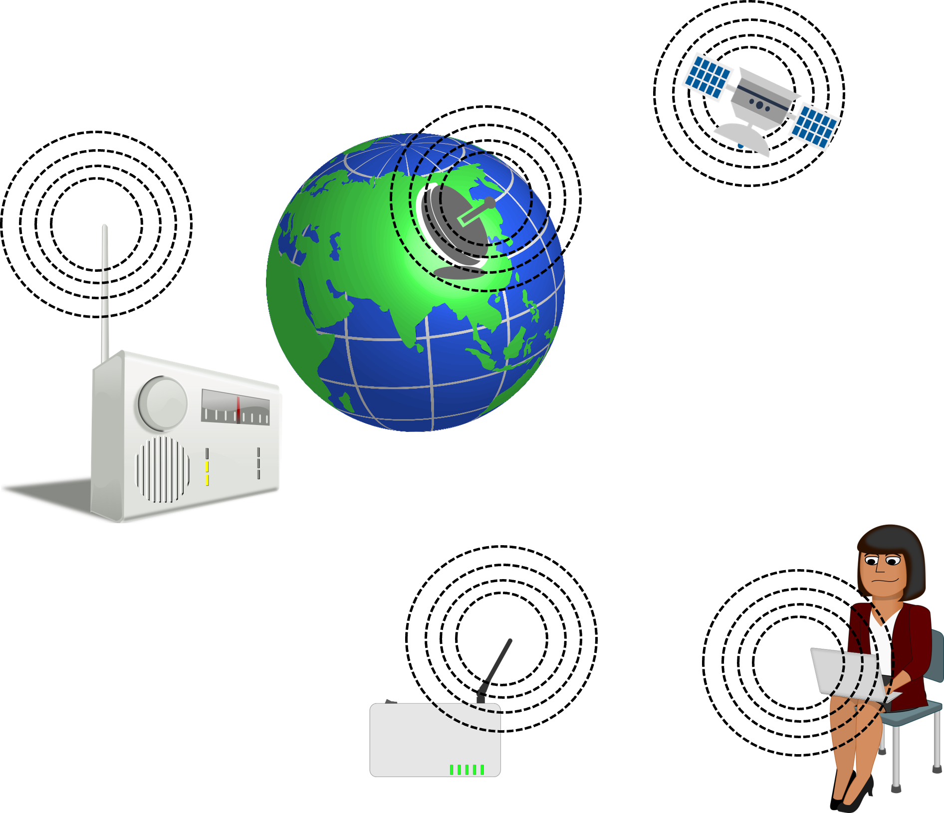
Everyday examples of radio communication
To answer this, it helps to start by looking at propagation in free space and the derivation of the Friis equation.
Free space model
In the article, "Propagation", we touched on the free space model which relates free space loss with distance (d):
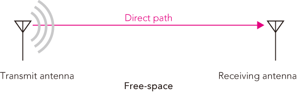
Free space transmission
As we will see, calculating the input power at the receiver does involve knowing the wavelength (therefore frequency) - so being an inherent property of an electromagnetic wave, does it mean it must be having an influence?
The quick answer is "no".
Radio waves are electromagnetic waves with oscillating electric and magnetic fields. For the same amount of power, all radio waves will travel the same distance irrelevant of frequency. If so why does wavelength appear in our calculation?
In this article we will find out.
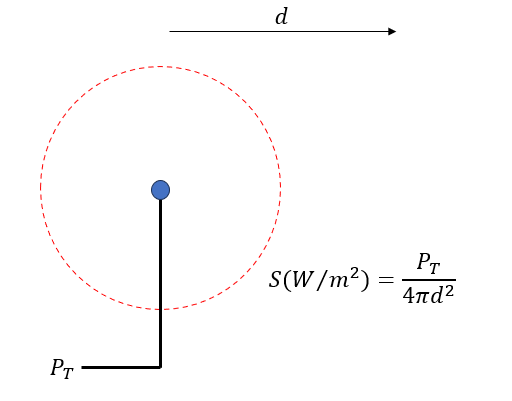
What is an isotropic radiator?
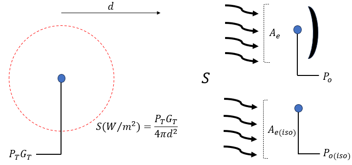
An isotropic radiator has a pattern that extends in all directions at a certain distance (d) from a point source. Naturally this pattern forms a sphere with a surface area (A) that changes with distance (d) from the source. We can define the power density (S) which is the available power per unit area equal to the input power (PT) divided by the area (A).
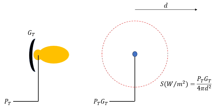
Equivalent isotropic radiated power or EIRP
Now let us imagine adding some sort of reflector forcing our radiation pattern into a narrow beam. This will increase the directivity of our antenna by an amount equal to the antenna gain (GT). Since the power density is only defined when the radiation pattern is a sphere, we can imagine an equivalent isotropic with input power equal to PT x GT.
The value PT x GT is known as the equivalent isotropic radiated power (EIRP) and is the amount of power we would have to put into an isotropic to achieve the same effective radiation as our antenna. Because of this, the available power per unit area (S) has now increased by a factor GT.
 For more information about working with antenna gain and EIRP, refer to this article.
What is the effective area of an antenna?
A receiving antenna is responsible for transforming the electromagnetic energy hitting it into electrical energy. This electrical energy is the power that is available to our receiver.
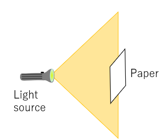
To help visualise this, imagine a light source such as a torch. Such light would spread out in a "cone" shape illuminating the walls and ceilings. Now if a piece of paper is held up in front, it will be illuminated by the torch. If a bigger sheet of paper is used, more light would hit it because of the larger area.
For an antenna to convert the incident radiation into power, it has to collect it through some imaginary area or aperture similar to how the paper is collecting light from the torch. This theoretical area is referred to as the effective area (Ae).
Effective area
If the available power at the antenna terminals is (Po), we can compare this to the power output by an isotropic antenna (Po(iso)) under the same receiving conditions. This ratio is the receiving antenna gain (GR) using an isotropic as a reference. Assuming all the incident radiation is converted to output power, then:
$$G_R = \frac{P_o}{P_{o(iso)}}=\frac{SA_e}{SA_{e(iso)}}=\frac{A_e}{A_{e(iso)}}$$
So why are we comparing our area to an isotropic? This is because the effective area of an isotropic has been well defined. The proof is mathematically complex and will not discussed here, but is written below:
$$A_{e(iso)}=\frac{\lambda^2}{4 \pi}$$
Friis equation derivation
The output power (Po) will be the effective area (Ae) multiplied by the power density (S) originating from the transmitter.
$$P_o=A_eS = A_e\frac{P_TG_T}{4\pi d^2}$$
Which means our output power (Po) in terms of receiver antenna gain (GR) will be:
$$P_o = A_{e(iso)}G_R\frac{P_TG_T}{4\pi d^2}$$
Knowing the effective area for an isotropic and putting this in our equation will give us our wavelength term:
$$P_o = \frac{P_TG_TG_R\lambda^2}{(4\pi d)^2}$$
This equation accounts for the transmit power, distance, frequency, transmit and receive antenna gains and is known as the Friis equation, named after the engineer (H.T.Friis). It should be clear that the frequency dependence occurs only because the equation is factoring in the effective area (which is dependent on the wavelength). Therefore it is in no way connected to the radiated power.
Propagation loss
If we re-arrange the above equation, expressing the propagation loss just in terms of distance and ignoring the influence of antenna gain (by fixing the gain to be 1 or 0 dBi), the difference between transmit and receive power will be:
$$Loss = \frac{P_T}{P_o} = \frac{(4\pi d)^2}{\lambda^2}$$
$$Loss (dB) = 20\log {\frac{4\pi d}{\lambda}}$$
We can realise that the lambda term relates the conversion of electromagnetic energy to electrical energy at the receive antenna - nothing to do with the propagation of the electromagnetic wave itself.
Increasing effective area
For an antenna receiving at a fixed frequency, increasing the directivity and gain will increase the effective area of the antenna.
This may seem counter intuitive as a more directive antenna means a narrower receiving angle. However even as the peripheral reception area decreases - the directivity will increase the effective area by an amount equal to the antenna gain (GR).
Since the effective area goes down when going from larger to smaller wavelengths (which places higher frequencies at a disadvantage compared to lower frequencies), you need to improve effectiveness at higher frequencies by using high gain antennas such as a parabolic antenna (which is do-able with high frequencies). The result is a more point to point communication such as one would see on satellites.
Conclusion
Hopefully it should be clear that both high and low frequencies will travel the same distance in free space. The problem is being so accustomed to using radios on earth that we automatically form expectations when it comes to high and low frequencies.
Propagation vs communication range
In free space, loss due to propagation is determined only by the distance from the transmitter, not frequency. Outer space is the closest approximation to free space, so one would expect to achieve the same communication range for any frequency.
However, the achievable communication range depends not only on propagation, but also optimising modulation techniques, antenna characteristics, sensitivity etc.
The Friis formula: Link budget and decibels
The formula for the link budget is modelled on the Friis equation, however the link budget also includes other losses and gains in the system (e.g. cable losses and amplifier gains). For more information on link budgets, refer to this article, "Link budget".
Typical link budget calculations are performed using decibel units (dB). The Friis formula is normally written in generalised form and does not use decibel units. Incorporating the Friis formula means allowing for input parameters (e.g. antenna gain in dBi) to be expressed in dB units.
