Data interfacing
Introduction
The radio module's function is to allow communication to take place between two devices by radio. While they contain all the necessary RF circuitry to do this in a single enclosure, they still require connection to a host CPU to allow data to be input or output. During transmission, the CPU sends data to the radio module's data input terminal and during reception receives data from the radio module's data output terminal. An example of a CPU connection is shown below for Circuit Design module MU-4, and Circuit Design SLR-434M connection examples can be found here.
MU-4 connection with CPU. Transmit data is input to MU-4 RXD and receive data is output from MU-4 TXD. Various control signals (such as CTS, RTS lines are included)
UART interface
UART is short for Universal Asynchronous Receiver Transmitter and has existed as far back as the 1960s. It is a piece of hardware that allows asynchronous communication between 2 devices. The term asynchronous means that both the sender and receiver do not use an external clocking signal. A clocking signal is important because the receiver requires timing information to correctly read the signal and determine if a bit was HIGH or LOW.
Before data comes in, the receive line is held in a HIGH ("idle") state. A START bit tells the receiver that a packet is about to arrive which results in the line going from HIGH to LOW. The receiver senses this change and uses this to derive the correct timing information so that the bit is always sampled in the center as shown below. A STOP bit signals to the receiver the end of one frame with the optional parity bit (PB) before it for basic error detection.
UART frame containing 8 bits or 1 byte with added parity bit. 8-bits is enough to encode alphanumeric characters as used in ASCII.
A CPU can contain up to several UART peripherals for serial communication with other devices such as PC or any device with a serial port. A device will have one terminal for transmitting (usually "TXD") and one terminal for receiving (usually "RXD") allowing two way communication. The UART bit rate, data length, parity, stop bit and flow control are configurable by the user.
Control signals
At minimum, the UART communication can be established just by using the TXD, RXD and GND lines. But in order for the 2 devices to agree when to send and receive data, there needs to be some control signals between both devices. This is common practice as one device maybe busy or one of the device's receive buffers are full. Without control or hardware flow, data maybe lost. Therefore UART peripherals include 2 extra lines known as CTS (Clear to Send) and RTS (Request to Send). When a device is ready to accept data, it will send a "request to send" signal from its RTS terminal to the CTS terminal on the second device.
MU-4 using CTS and RTS (in red) together with TXD and RXD.
UART and RS232
RS232 stands for "Recommended Standard 232" and historically has been used to allow communication between PC and peripheral devices such as a modem. It has been largely replaced with the more familiar USB (Universal Serial Bus) but as an established technology still finds uses in machine communication, point to point links and other areas with lower speed and shorter ranges. It is a form of serial communication and frequently linked with UART, however RS232 explicitly states the voltage levels, slew rates, pin definitions, connector types that are to be used. Below is a capture of an RS232 signal.
RS232 from the PC. (transmitting the character 'a' or 0x61 at 9600 bps, no parity, 1 stop bit). Note how RS232 has an inverse relationship between bit symbol and voltage level.
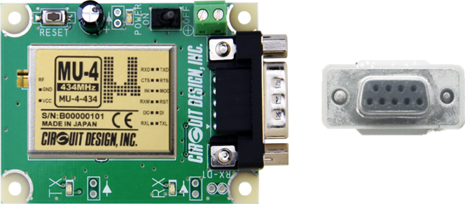
The MU-4 Evaluation Board uses RS232 to connect to a host PC using 9-pin DE-9 connector.
Even though the RS232 interface has been improved over time, its design limits it in distance (below 15 m originally) and bit rate (below 20 kbps originally). It was also limited to 1:1 communication between devices at full duplex.
Further improvements came with the development of RS422 and RS485 interfaces which introduced differential signaling allowing much further distance / higher bit rates to be reached. Multipoint communication, 1:N (RS422) and M:N (RS485) became possible with full duplex capability.
Since RS232 only specifies hardware protocols, it is possible for UART peripherals to drive RS232 signals and communicate with the PC e.g. using terminal software. In other words, Circuit Design modules like the MU-4 can be controlled from a PC and a user program. However care must be taken as the RS232 voltages are much higher (in addition to being inverted) than those found in UART and an interface (such as ADM3222 IC) is necessary. Directly connecting the radio module or a CPU with RS232 signals will likely cause damage.
Synchronous communication
Previously we discussed how UART does not use an external clock signal to synchronise the sender and receiver. The receiver used the START bit in the data to extract timing information. When an external clock is used, the interface is called synchronous. Since the timing between sender and receiver is now matched using the clock signal, it is not necessary to include the START and STOP bits in the data. This reduces the data payload to be transmitted. Of course it does require a third signal line (clock) in addition to the TXD and RXD. An example of a Circuit Design module that uses synchronous interface is STD-503.
STD-503 using synchronous interface (shown in red). The CPU serial input and output is shown as "SI" and "SO".
Example standards
Examples of synchronous communication are SPI (serial peripheral interface) developed by Motorola in the mid 1980s and I2C (pronounced as "I squared C") developed by Philips Semiconductors in 1982. There are many articles online for details of this and other standards.
If a CPU's UART allows the option of synchronous communication using a separate clock, it is called USART (Universal Synchronous Asynchronous Receive Transmit) and will include a terminal for a clock signal.
Transparent interface
Circuit Design products are described as "transparent", meaning it allows the user to develop own communication protocol instead of following a protocol under a particular device. From the RF module's point of view, it can mean "what goes in, comes out".
However Circuit Design's modems, SLR-434M and MU-4 are not transparent (the MU-4 does have the option for transparent interface) and so the user must follow the command control protocol prescribed by Circuit Design. To understand this, we can look at the MU-4 command protocol for sending data.
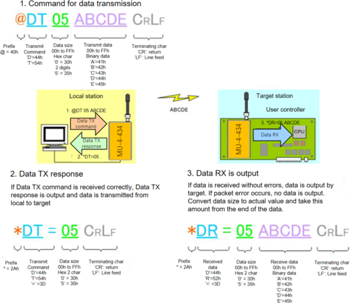
The command protocol for sending data using MU-4
In the example above, the user data we want to send are the characters 'A', 'B', 'C', 'D', 'E'. If we want to send these in command mode, we have to follow the protocol laid out by Circuit Design. This means padding the user data with extra bytes '@', 'D', 'T', '0', '5', 'CR', 'LF' to create a data frame. The result is the user can incorporate our command and protocol format for easy control and reliable RF communication.