Antenna types and parameters
Why do we have different antenna types?
Because there are many applications involving radio, the way the radio wave should be transmitted, received and propagated will vary depending on the application requirements. This makes the antenna a critical component in any communication system, so it is important for the user to select the correct type of antenna. There is no point in investing in a good performance radio and then forgetting about the antenna.
There are many specifications that determine how an antenna will perform, but we can list them as below:
Antenna specifications
Frequency of use
The physical properties of the antenna is generally related to the frequency of operation. For example in another chapter, we established that resonance occurs when the dipole is a half wavelength long (see How antennas radiate?). Since frequency determines the wavelength, this means that an antenna will only be efficient at one frequency. While this in itself is no problem, it does mean that antenna size can vary from being small (e.g. WiFi router antennas at 2.4 GHz) up to very large sizes (e.g. AM broadcasting towers at only few hundreds of kHz).
In the radio spectrum frequency bands are generally allocated by application, so in each one you will generally find similar sized antennas being used.
Bandwidth
Previously we mentioned that antennas are efficient at only one frequency. In practice the efficiency drops gradually the further away the frequency is from the resonant frequency allowing the antenna (in most cases) to work satisfactorily over the desired frequency range. For example, a single antenna can satisfactorily receive all signals on the commercial FM broadcast band.
For general purpose reception, there are antennas that have a wide bandwidth allowing them to receive signals from several bands, e.g. a discone antenna. However, antenna performance maybe degraded as a result.
Polarisation
In the last chapter, it was mentioned that the radio wave (or specifically the electric field) can oscillate in the horizontal or vertical plane. This depends on how the antenna is installed at the transmitter and therefore the receiving antenna must be orientated in the same way for communication.
Gain
An isotropic antenna is a point source that radiates in all directions equally.
Normal antennas do not radiate equally in all directions and maximise radiation in one direction while minimising it in other directions. We say that the antenna exhibits directivity or gain in the direction of peak radiation. To express gain as a value we compare this peak level against the level from an isotropic antenna and look at the dB difference. This difference is the gain and expressed in dBi.
If you take the example of a dipole antenna and compare its radiation pattern to an isotropic, we see that the dipole maximises radiation perpendicularly and minimises it at the tips. It should be clear that to maximise communication efficiency, the receiving antenna should face this direction of maximum radiation.
For fixed point to point links such as satellite and broadcast television, antennas will usually have very high gain/directivity (e.g. 17dBi) since there is only one line of communication. For mobile communications, such antennas will need to have a more omnidirectional coverage.
VSWR
The VSWR (voltage standing wave ratio) is a measure of how much of the input power is being converted to radiation (see Impedance and standing wave ratio) and is specified on all antenna datasheets, usually as a ratio eg. 2:1 or 1:1. You will normally find the VSWR plotted against frequency where VSWR ranges from 1 (ideal) to infinity. The target frequency shows up as a peak that is at or approaching the VSWR of 1. This is normally the frequency the antenna was designed for.
VSWR of ANT-400-R
Antenna impedance
The antenna impedance (in ohms) is the impedance value seen at the antenna terminals. This does not mean the DC resistance, but the radiation resistance (whose job is to convert the incoming signal to radiation) which varies with the frequency. As a result using the antenna outside of its designed frequency will change its feed point impedance to an incorrect value. An incorrect value will cause the antenna to reflect some of the RF signal back and produce high VSWR.
When the antenna is used at its correct design frequency its feed point impedance will match the impedance of the feeder and the rest of the system (and produce VSWR of 1). Usually radios and antennas are designed around 50 ohm impedance. However where impedance cannot be matched, an impedance transformer or matching unit should be used.
If there is impedance mismatch, the VSWR will no longer be 1 and the antenna will not radiate efficiently.
Radiation patterns
The radiation pattern is a visual representation of the radiation emission from an antenna. Depending on the application, antennas may need 360 degree coverage or in the case of fixed point to point links, the antenna only needs to transmit in front. Below are the radiation patterns for dipole, yagi and parabola.
Antennas by application
Below are the basic types of antenna and applications in order of increasing gain.
| Antenna | Example photo | Gain | Description |
|---|---|---|---|
| Isotropic |  |
0 dBi | Does not exist in reality but used to compute gain of practical antennas. |
| Standard Dipole | 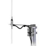 |
+2.14 dBi |
In a dipole antenna, there are 2 radiating elements, each 1/4 wavelength long producing an overall dipole length of 1/2 wavelength. Because it is a complete antenna, it does not require a ground plane to operate such as in a monopole antenna. This makes it easier to install anywhere with no impact in performance. When installed vertically, it can provide 360 degrees coverage in the horizontal plane. Example uses include amateur radio, VHF/UHF base stations. |
| Whip / Monopole |  |
+2.14 dBi |
If we take a dipole and remove one of the elements then install it over a ground plane, the antenna can still radiate. This is possible because the ground is able to reproduce the radiation of the dipole by "mirroring" the missing element. The "monopole" refers to there being only one element instead of two and when using coax feed the outer shield is connected to the ground plane. The main advantage over a dipole is the shorter length (approximately half as long as dipole) and can be installed easily on any metallic surface. The disadvantage is that the performance is dependent on the quality of the ground plane. Example uses include mobile and handheld radios, short range devices. |
| Yagi-Uda |  |
High dep. on elements |
A Yagi-Uda antenna consists of several parasitic elements placed in front of the driving element (usually a dipole) with one rear element acting as a reflector. The extra elements increase the forward gain while reducing gain to the side and rear. The gain is increased over a single dipole but only in the forward direction so cannot be used for 360 degrees coverage.
Example uses include fixed point to point links such as UHF Television reception. |
| Parabolic |  |
Very high, dep. on dish size |
A parabolic or dish antenna uses a concave reflective surface that focuses the RF onto a central feed (usually a small dipole or similar). The gain depends on the size of the dish so for weak signal reception dish sizes can be up to many meters in diameter. Since high gain is also produced by using shorter wavelengths, dish antennas are commonly used in fixed line of sight communications above 1 GHz.
Example uses include satellite downlinks (eg. Television) and uplinks, Microwave communication links, radio astronomy. |
Monopole antennas
A half wave dipole operating at the correct frequency is the most optimum antenna. However at lower frequencies, the size of the dipole can become impractical.
Since the dipole is electrically symmetrical, it is possible to mirror the active half over a conductive ground surface. The earth is not a perfect conductor but very often used as ground due to its large mass. An AM broadcast tower is such an example.
The ground does not always need to be physical earth, but can be represented using flat metal plane. For practical construction, the ground plane can be simulated using radials.
Folded monopole antenna
This antenna (shown below) is a similar version but it is an example of an antenna that can provide a path to ground for accumulated charges. This is useful if the antenna is exposed to thunderstorms or accumulates excess static. The conducting element loops back on itself to the ground plane (which is grounded via the coax braid or tower). This DC short presents a high impedance to RF so it does not affect reception, but any stray voltages can be diverted to ground.
Left - normal 1/4 wave monopole and (right) a folded 1/4 wave mono pole.
