Impedance and Standing wave ratio.
Introduction
When looking at radio equipment, we often see terms such as characteristic impedance, antenna impedance, transmitter impedance and so on. This article explains the importance of matching impedances when building a radio system and the significance of VSWR (voltage standing wave ratio).
What is impedance?
In electrical circuits the term resistance, R (or ohmic resistance) is used to describe elements that impede the flow of electrons in a circuit e.g. resistors.
However since radio uses high frequency RF that compose of time varying sinusoidal voltages and currents, we have to consider not just resistance, but also reactance ( denoted by the symbol "X").
Reactance elements in RF circuits are made up of capacitors (producing negative reactance) and inductors (producing positive reactance). The term "impedance" generally refers to the combined total of resistance and reactance. In complex notation it is:
$$Z [Ω] = R + Xj$$
Since reactance represents "stored energy", it is not very useful. The resistance, R (generally called radiation resistance) which represents conversion to RF energy, we want to maximise this value.
Antenna and cable impedances
Now that we have explained the presence of inductance and capacitance reactance that contribute to the total impedance of the RF circuit, we can start to understand impedance for all RF components.
Transmission lines such as coaxial cables consist of an inner conductor and outer conductor (or shield) as shown below.
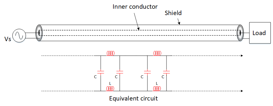
Even though there are physically only 2 conductors, to a transmitter it sees a cable seemingly made out of distributed inductance and capacitance as shown in the equivalent circuit. In other words, the transmission line has a characteristic impedance, Zo. Cable characteristic impedances can be any value and depend on the dimensions and dielectric properties of the cable. But mostly they are sold as 50 or 75Ω with the value printed on the outer jacket as shown.

Why impedance matching is important here is if the load impedance and the cable's characteristic impedance are the same (Zload = Zo), theoretically, the transmitter sees the load as if the transmission line was not there. The transmitter can transfer all the energy to the load. However real transmission lines have losses, so this transfer can never be completely ideal.
Like the cable, the antenna may only consist of metal conductors but it too contains reactive components. Below is an image of the distributed inductances and capacitances along the antenna as seen by the system.
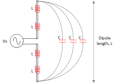
It follows that the antenna also has an impedance that varies with the physical properties of the antenna such as length and thickness of the dipole elements. Later we will see how the antenna impedance is linked to the antenna resonant point and VSWR.
Antenna impedance and resonance
In an another article, we mentioned resonance and how setting the antenna dipole length to 1/2 wavelength manages to achieve this condition. The dipole contains reactance in the form of distributed capacitance and inductance. When adjusting the dipole length, the resonant point occurs when reactance "X" drops to near zero as seen in the following table:
| Dipole length, L | Reactance, X | Impedance, Z |
|---|---|---|
| L > λ/2 | +X | Antenna is Inductive |
| L = λ/2 | 0 | Antenna is Resonant, Z = 72Ω |
| L < λ/2 | -X | Antenna is Capacitive |
At the resonant point, the antenna presents to the transmitter a pure resistance of about 72Ω. Since normal radio systems don't operate in a vacuum the actual value is closer to 50Ω which matches up perfectly with our coaxial cable.
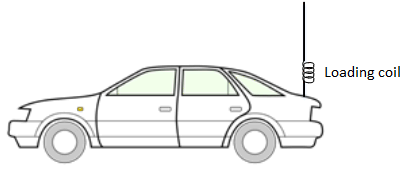
Making the dipole length longer or shorter than 1/2 wavelength will increase the reactance and the antenna will not be properly matched to the rest of the system. In some applications where the environment does not permit full size antennas to be installed, one would have to use antennas shorter than half wavelength (making the antenna more capacitive). By adding some inductance in the form of a "loading coil" to the base, this extra capacitance can be cancelled out.
Voltage Standing Wave Ratio <VSWR>
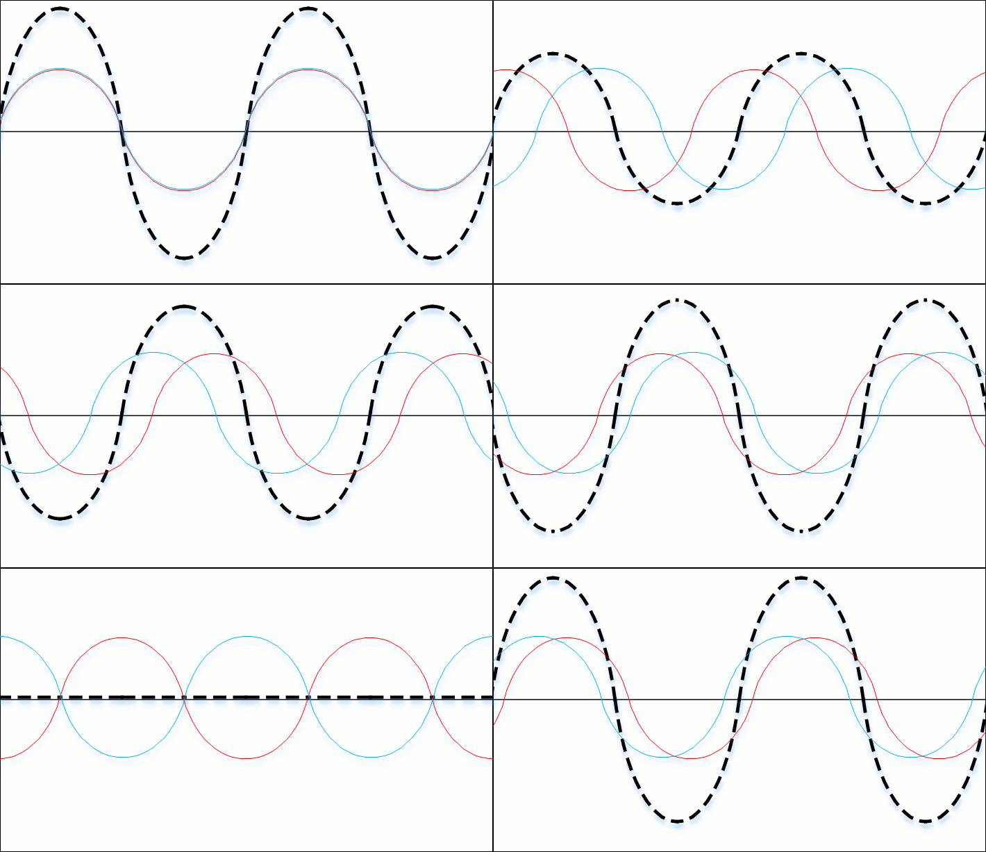
When impedance mismatch exists between any load (e.g. antenna) and the rest of the system, power from the transmitter flows to the antenna and a fraction of the power is reflected back towards the transmitter. These forward and reflected waves interfere with each other to produce standing waves along the transmission line. By looking at the maximum and minimum voltage amplitude of the standing wave, we can calculate the VSWR.

![]()
Reflected power is not desirable as ideally all power from the transmitter should be absorbed by the load. The standing waves can cause heating effects in the cable or damage to the transmitter.
Reflection coefficient.
Reflection coefficient or "Γ" describes the tendency of the forward wave to reflect back towards the transmitter instead of being absorbed by the load. This depends on the load, ZL and cable impedance, Zo described by the equation:
$$Γ = \frac{Z_{L}-Zo}{Z_{L}+Zo}$$
By substituting various values we can summarise what happens to Γ when we change the value of the load as follows:
| Load, ZL | Reflection coefficient, Γ | % Reflected power |
|---|---|---|
| Open circuit | +1 | 100% |
| ZL = Zo | 0 | 0% |
| Short circuit | -1 | 100%, inverted |
- The reflection coefficient can only be between -1 and +1.
- The reflection coefficient should be zero when there is no reflection.
Once we know the reflection coefficient, Γ we can calculate VSWR through this equation. The |Γ| represents the magnitude only (in the above table, both"+1" and "-1" are equivalent to "1").
$$VSWR = \frac{1+|Γ|}{1-|Γ|}$$
If we include the VSWR calculation in our previous table and consider magnitude of reflection coefficient:
| Load, ZL | Reflection coefficient, |Γ| | % Reflected power | VSWR |
|---|---|---|---|
| Open circuit or short circuit | 1 | 100% | ∞ |
| 0.8 | 64% | 9.0 | |
| 0.6 | 36% | 4.0 | |
| 0.4 | 16% | 2.3 | |
| 0.2 | 4% | 1.5 | |
| ZL = Zo | 0 | 0% | 1 |
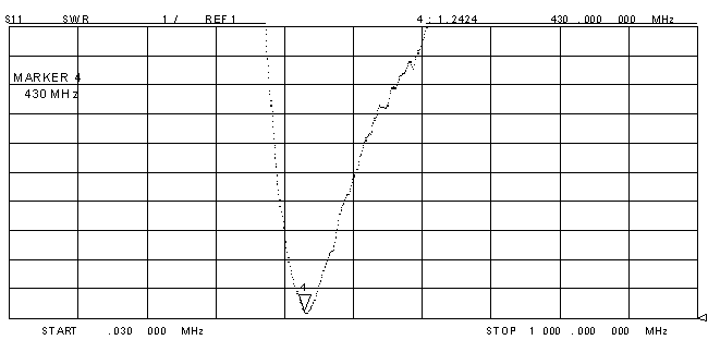
The VSWR ranges from 1 or 1:1 (ideal) to infinity. When the load or antenna impedance, Z (whether real or complex) changes we get different values of VSWR that fall in this range. In particular since antenna impedance depends on the dimensions of its conductors which are themselves measured in wavelengths of the operating frequency, there will be an optimum design frequency where the antenna is closely matched to Zo and produce a low VSWR. For example the ANT-400-R, has an SWR chart as below. The design frequency for this antenna is at the bottom peak where VSWR is 1.2424.
Conclusion
VSWR can be used in most cases to determine efficiency of your radio system, however it does not always predict antenna performance. For example, a 50 ohm resistor or "dummy load" will give a perfect VSWR of 1.0, but would make a very poor antenna.
When its not possible to establish a good impedance match to your antenna, matching unit between the transmitter and antenna can be used. However this only allows the transmitter to see a perfect load and may not necessarily improve antenna performance.
