![]()
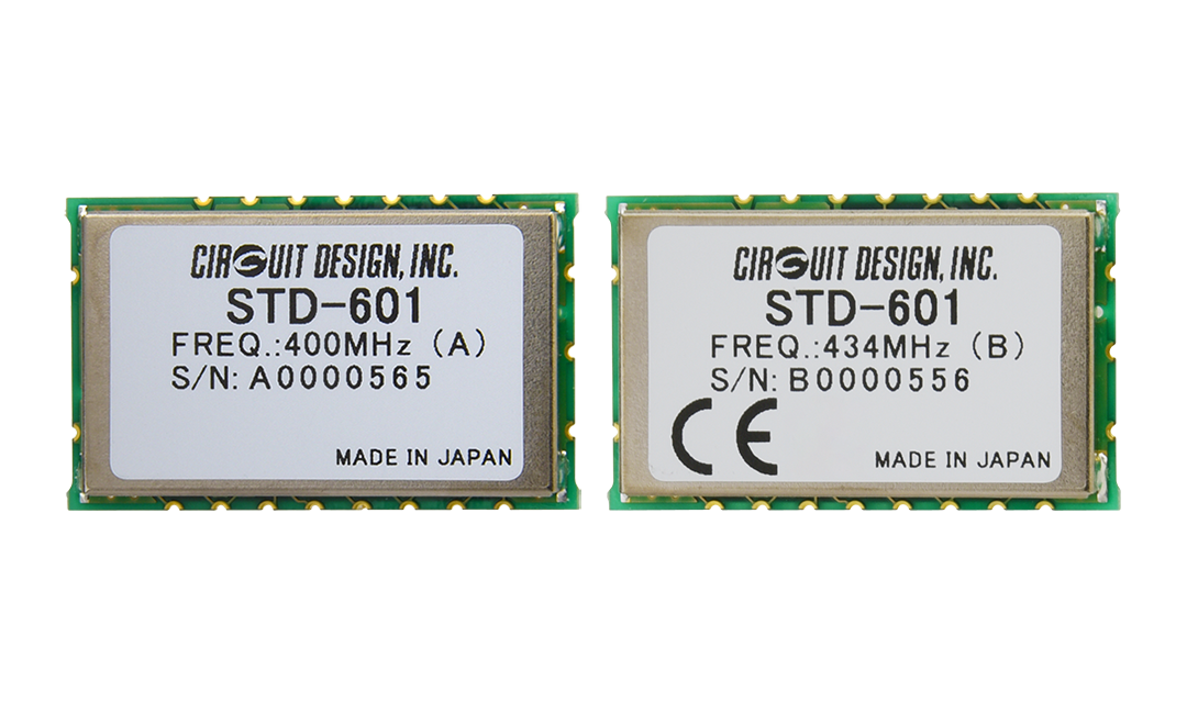
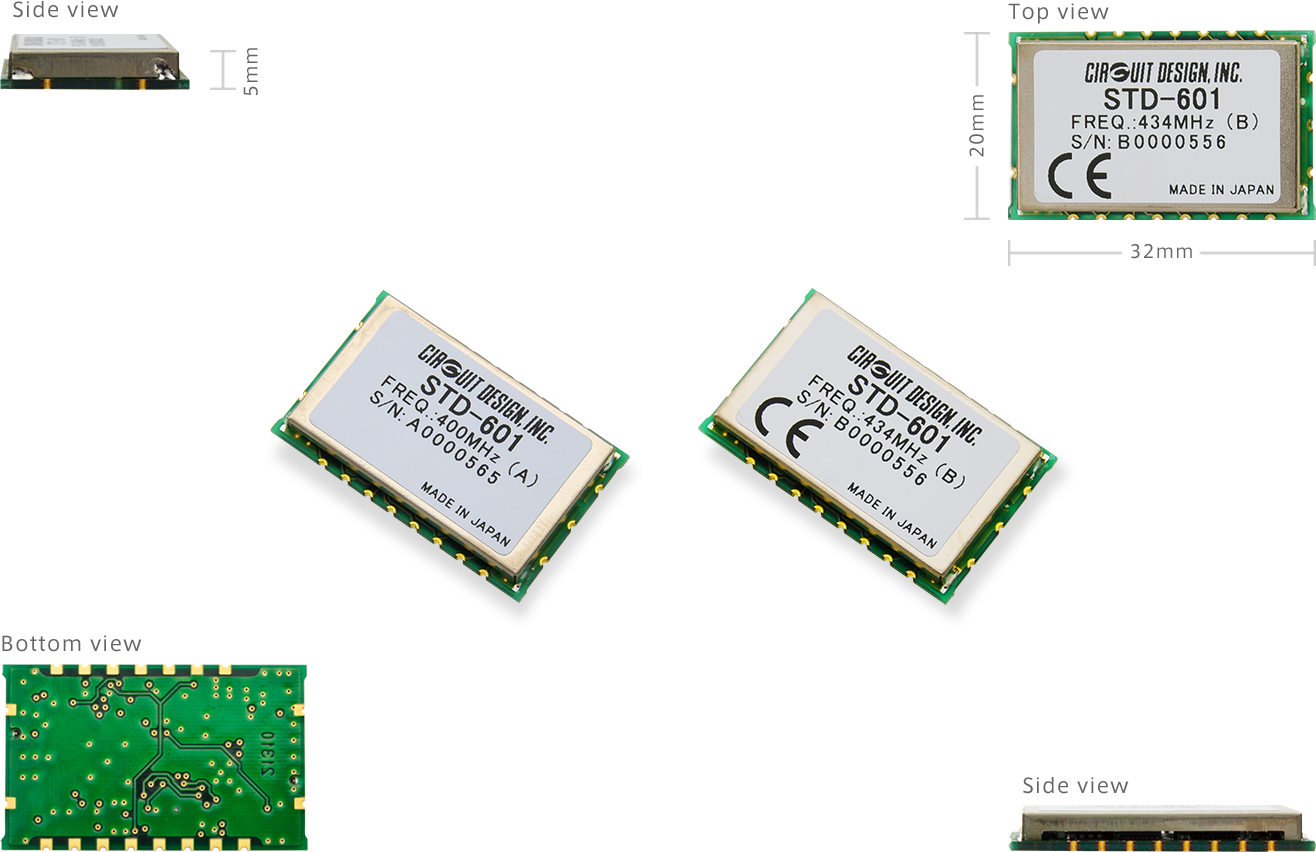
The STD-601 is a miniature transceiver designed for industrial remote control and telemetry applications. The STD-601 has a simple serial interface and allows own communication protocol to be used. The RF Power, Data rate and Channel can be set through the use of dedicated serial commands.
The STD-601 434 MHz operates on the 434 MHz only and carries the CE marking and UKCA marking.
| Model name | Band (MHz) | RF power (mW) | Data rate (bps) | Certification | Consumption (mA) |
|---|---|---|---|---|---|
| STD-601 400 MHz |
429 434 447 458 |
50 / 25 / 20 / 10 / 5 / 1 | 1,200 / 2,400 / 4,800 / 9,600 / 19,200 | No | 35 (TX 10 mW) |
| STD-601 434 MHz |
434 | 10 / 5 / 1 | 4,800 / 9,600 | Yes (CE) |
26 (TX 10mW) |
Features
[ Common ]
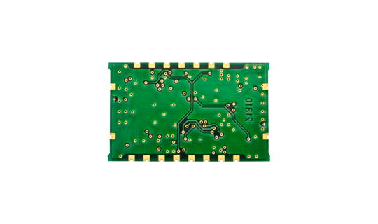
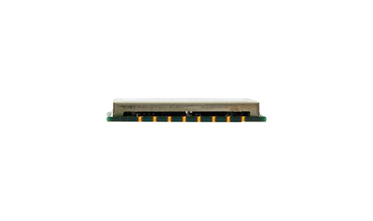
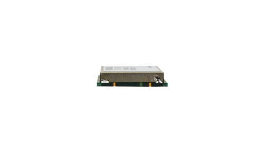
- Small 20 x 32 x 5 mm SMD
- Transparent interface for data input and output
[ STD-601 400 MHz ]
- Selectable bands possible within wide frequency range.
- 429 / 434 / 447 / 458 MHz
[ STD-601 434 MHz ]
- 434 MHz European ISM band
- Low consumption current
- 26 mA (TX 10 mW / 3 V)
- 19 mA (RX) - RED compliant (EN 300 220)
- Radio Equipment Regulations 2017 (UK)
Applications
- Industrial telecontrol
- Telemetry Systems
Specifications
STD-601 434 MHz
Common
| Parameter | Specification | Remarks |
|---|---|---|
| Applicable standard | RED compliant (EN 300 220) UK Radio Equipment Regulations 2017 |
CE marking and UKCA marking acquired |
| Communication method | One Way, Half Duplex | |
| Emission type | F1D | 2-GFSK |
| Frequency | 433.0750 to 434.7750 MHz | 12.5 kHz step |
| Number of RF channels | 137 channels | |
| Channel spacing | 25 kHz | |
| RF bit rate | 4,800 / 9,600 bps | |
| Pulse width | Min. 208 us / Max. 10 ms Min. 104 us / Max. 10 ms |
4,800 bps 9,600 bps |
| Supply voltage | 3.0 to 5.0 V DC | |
| Supply current | 26 mA typ. (TX 10 mW) 19 mA typ. (RX) |
|
| Operating temperature range | -30 to +75 degree C | |
| Dimensions | 20 x 32 x 5 mm | |
| Weight | 4.5 g |
Transmitter Part
| Parameter | Specification | Remarks |
|---|---|---|
| RF output power | 10 / 5 / 1 mW | Conducted 50 ohm |
| Deviation | +/-3.75 kHz (PN9 9,600 bps) +/-2.2 kHz (PN9 4,800 bps) |
|
| Data input | Digital L = GND, H = Vcc | |
| Spurious emission | < -54 dBm (47 - 74 M, 87.5 - 118 M, 174 - 230M, 470 - 862 MHz) < -37 dBm (Other frequencies < 1000 MHz) < -30 dBm (> 1000 MHz) |
|
| Adjacent channel leakage power | < -37 dBm |
Receiver Part
| Parameter | Specification | Remarks |
|---|---|---|
| Receiver type | Single superheterodyne | |
| Maximum input level | 10 dBm | |
| Receiver sensitivity | -113 dBm (9,600 bps) -117 dBm (4,800 bps) |
BER 1% |
| Adjacent channel selectivity | > 50 dB (9,600 bps) > 50 dB (4,800 bps) |
+/-25 kHz +/-12.5 kHz |
| Blocking | 70 dB | |
| Spurious radiation | < -57 dBm (< 1000 MHz) < -47 dBm (> 1000 MHz) |
|
| Data output | Digital L = GND, H = Vcc |
Interface
| Parameter | Specification | Remarks |
|---|---|---|
| Data Interface ( DI / DO ) |
L = GND H = VCC, Asynchronous | Transparent |
| Command interface (TXD / RXD) |
UART 9,600 / 19,200 / 38,400 bps 8 data bit, No parity, 1 stop bit |
*Unless otherwise specified, specifications are typical values obtained under 9600bps, 10mW, 25C, 434MHz, 3V
*Specifications are subject to change without prior notice
STD-601 400 MHz
Common
| Parameter | Specification | Remarks |
|---|---|---|
| Communication method | One Way, Half Duplex | |
| Emission class | F1D | 2-GFSK |
| Frequency | 429.1750 to 429.7375 MHz | 429 MHz |
| 433.0750 to 434.7750 MHz | 434 MHz | |
| 447.2750 to 447.9875 MHz | 447 MHz | |
| 458.5000 to 459.1750 MHz | 458 MHz | |
| Number of RF channels | 47 channels 137 channels 59 channels 28 channels |
429 MHz 434 MHz 447 MHz 458 MHz |
| RF bit rate | 1,200 / 2,400 / 4,800 / 9,600 / 19,200 bps | |
| Supply voltage | 3.0 to 5.0 V DC | |
| Supply current | 35 mA typ. (TX 10 mW) 58 mA typ. (TX 50 mW) 19 mA typ. (RX) |
|
| Dimensions | 20 x 32 x 5 mm | |
| Weight | 4.5 g |
Transmitter Part
| Parameter | Specification | Remarks |
|---|---|---|
| RF output power | 50 / 25 / 20 / 10 / 5 / 1 mW | |
| Deviation | +/-3.75 kHz (PN9 9,600 bps) +/-2.2 kHz (PN9 4,800 bps) |
|
| Data input | Digital L = GND, H = Vcc | |
| Spurious emission | < -54 dBm (47 - 74 M, 87.5 - 118 M, 174 - 230M, 470 - 862 MHz) < -37 dBm (Other frequencies < 1000 MHz) < -30 dBm (> 1000 MHz) |
|
| Adjacent channel leakage power | < -37 dBm | 9,600 bps +/-25 kHz |
Receiver Part
| Parameter | Specification | Remarks |
|---|---|---|
| Receiver type | Single superheterodyne | |
| Maximum input level | 10 dBm | |
| Receiver sensitivity | -113 dBm (9,600 bps) -117 dBm (4,800 bps) |
BER 1% |
| Adjacent channel selectivity | > 50 dB (9,600 bps) > 50 dB (4,800 bps) |
+/-25 kHz +/-12.5 kHz |
| Blocking | 70 dB | |
| Spurious radiation | < -57 dBm (< 1000 MHz) < -47 dBm (> 1000 MHz) |
|
| Data output | Digital L = GND, H = Vcc |
Interface
| Parameter | Specification | Remarks |
|---|---|---|
| Data Interface ( DI / DO ) |
L = GND H = VCC, Asynchronous | Transparent interface |
| Command interface (TXD/RXD) |
UART 9,600 / 19,200 / 38,400 bps 8 data bit, No parity, 1 stop bit |
*Unless otherwise specified, specifications are typical values obtained under 9600 bps, 10 mW, 25 C, 434 MHz, 3 V
*Specifications are subject to change without prior notice
External View
Operation Guides
| Version 3.0 (STD-601 400 MHz) | |
|---|---|
| Version 4.0 (STD-601 434 MHz) |
Supplementary Information
| Demonstration of the evaluation board for STD-601 |
|---|
Certifications
| DoC for CE (STD-601 434 MHz) | |
|---|---|
| DoC for UKCA (STD-601 434 MHz) |
Parts Change Notice (PCN)
| PCN2391001 (Oct. 2023) | |
|---|---|
| PCN2116001 (Sept. 2021) |
Evaluation Tools: TB-STD601
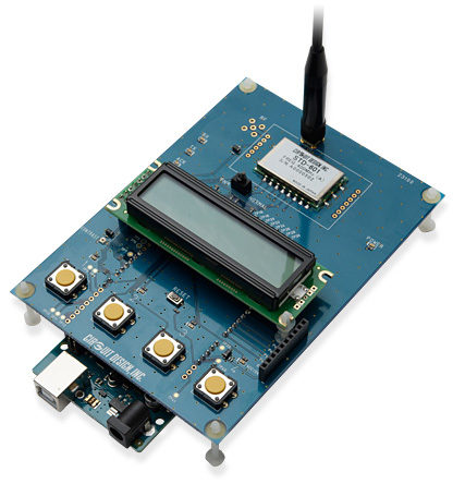
The test board TB-STD601 allows the STD-601 to be used in combination with Arduino MEGA 2560 to make simple switching and packet tests. An Arduino sample program* is included together with Windows setting interface to allow easy setup and control of the STD-601 module. As well as using the sample program, the user can develop own code to control the STD-601.
* Source code is available by email free of charge – visit the Documents page for details.
Features
- LCD screen
- 4 push buttons and 4 LEDs
- USB port
- 8 IO/Analogue Ports
- Receive / Transmit LEDs
- Packet Test Function
- Windows setting interface
- Arduino sample program (C++)
- TX/RX/ACK LED indicator
External View
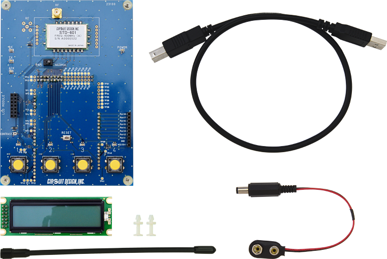
RF Module (STD-601) x 1
Display x 1
Spacer x 2
Antenna (ANT-400-SW) x 1
USB Cable x 1
Battery clip x 1
Adaptor Board: ADP-A-STD601, ADP-B-STD601
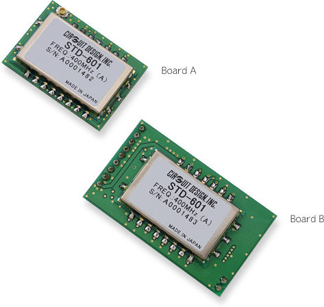
Each board, ADP-A-STD601 and ADP-B-STD601 contains CPU and dipswitches allowing the user to set the STD-601 parameters without any need to develop separate setting program. Parameters such as frequency band, RF power and bit rate can be set using the dipswitches.
When used in combination with the boards it allows user to easily setup communication by setting parameters using the dip switches and applying user data to the data in and out pins.
The adaptor board allows CDP-02 users to test the STD-601 using their existing CDP-TX-02E-R and CDP-RX-02E-R footprint and pin layouts. By allowing this compatibility, existing CDP users can evaluate the STD-601 quickly and easily without modifications.
Features
- Onboard dip switch to conveniently set STD-601 band, RF power, channel and bit rate
- No need to make setting program
- Convert STD-601 pin layout to CDP-TX-02E-R and CDP-RX-02E-R
- Board size matches those of CDP-TX-02E-R and CDP-RX-02E-R
- CDP module users can make communication test with STD-601 easily.
- Useable with STD-601 400 MHz and 434 MHz *
* Both boards include STD-601 400 MHz module. For STD-601 434 MHz module please specify when ordering.
Accessories


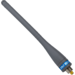
ANT-01-R
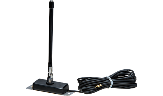
Antenna with extension coaxial cable for the receiver.
- Requires female connectors SJ050011, SJ060011.

SJ050011, SJ060011
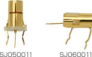
These female connectors fit onto the SP060022 connectors for PCB mounted connections. Please refer to the part numbers below.
![[ Video ] [ STD-601 ] - Introducing the official STD-601 evaluation board that uses Arduino MEGA 2560.](https://www.cdt21.com/wp/wp-content/uploads/2023/01/std-601_demonstration-of-the-evaluation-board.png)
- What is the difference between STD-601 434 MHz and 400 MHz version?
- Referring to STD-601 operation guide, is it possible to use the LOW signal event on the INT terminal to confirm module initialisation?
- What is transparent interface?
- Can I connect Circuit Design modules to Arduino or Raspberry Pi?
- I want to put the RF module in my enclosure? What do I need to be careful of?
- There is a problem with communication range. What is the problem? What should be checked?
- How should the antenna be handled?
- I need help in selecting a CPU to control my module?
- Can Circuit Design module communicate with a tablet?
- I'd like to use my own antenna on your module. Where can I find the suitable connector (e.g. SP060022)?