Digital modulation
Introduction
In another article, Analogue modulation, we talked about analogue communication systems. Analogue modulation involves modulating a radio frequency carrier directly with a continuously varying signal (such as a voice signal) and then at the receiver, it is demodulated back to the original signal. Thus the voice signal is recovered, amplified and can be fed to a loudspeaker. Various techniques such as AM, FM and PM were discussed.
Moving on from this topic, in this article we will discuss digital communication and digital modulation techniques and how they are used to transport non-continuous signals such as binary or serial data.
Difference between analogue and digital communication
Example of analogue communication
An example of an analogue communication system is a typical AM or FM radio broadcast. The microphone converts the voice into a continuously varying electrical signal. This signal is amplified and passed to the modulator where it modulates a radio frequency carrier. For this Frequency Modulation (FM) or Amplitude modulation (AM) is used. The modulated radio frequency signal is amplified and delivered to the station antenna for wireless transmission using radio waves.
At the receiver the radio wave is picked by the receiver antenna and converted back to the radio frequency signal. The signal is amplified and demodulation extracts the original voice signal from the carrier. This is amplified and fed into a loudspeaker.
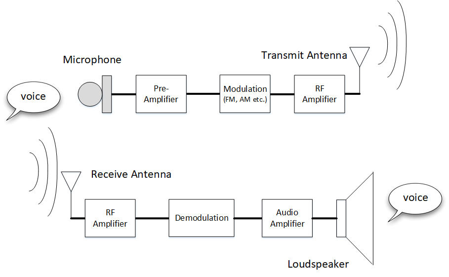
Voice broadcast using FM or AM.
Example of digital communication
While analogue communication transmits a continuous signal, digital communication on the other hand is concerned with transmission of a bit stream. If the signal in the time domain could be viewed, we would see a series of pulses. To convert this to a bit stream, the signal is sliced at time intervals of T and the value at each interval passed through a threshold. For example, if the time domain signal varies from 0 to 1V, and the threshold level is chosen to be 0.5V, the output value can be interpreted as digital bit 1 (> 0.5V) or a 0 (< 0.5V).
A common example of digital communication is the exchange of data between 2 computers on a network as shown below. A device called a modem converts the digital pulses to a signal suitable for transmission over a communication medium such as radio or telephone.

Digital communications taking place between computers
Digital communication over radio include digital television broadcasts (DVB-S2, ISDB etc.) , digital radio (DAB etc.) , GPS systems and mobile phone communication. In the next section, we will talk about how to modulate these bit streams so they can be transmitted over radio waves.
How do we transmit a bit stream?
A bit stream is just a signal with transitions from LOW to HIGH voltage levels instead of continuous variations. In analogue communication, we change the radio carrier's amplitude (AM), frequency (FM) or phase (PM) in response to the input signal. If a similar technique is applied to digital signals, the output will be amplitude, frequency or phase shifts (where each shift is a transition from 0 to 1 and 1 to 0). The 3 main methods used to modulate digital signals are amplitude shift keying (ASK), frequency shift keying (FSK) and phase shift keying (PSK).
ASK
In the article, Analogue modulation, we talked about amplitude modulation or AM. By varying the amplitude of the radio wave carrier with our message signal, m(t) we can transmit analogue information such as a voice signal. The result is a radio wave carrier, s(t) with amplitude fluctuations.
If instead of a continuous signal we input a bit stream, the result is a radio wave carrier with changes in amplitude corresponding to the "HIGH (1)" and "LOW (0)" level in our signal. This is known as Amplitude Shift Keying or ASK.
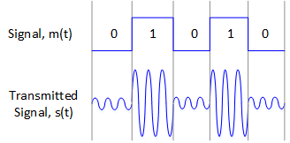
ASK modulation
While the hardware is simple to implement, it inherits the same weaknesses as AM - most notably information carried by variations in amplitude makes it highly susceptible to noise. In digital systems, since the receiver is only determining a HIGH and a LOW level, these noise fluctuations (if not too large) can be filtered out.
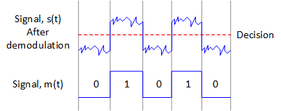
Demodulated ASK signal with noise
ASK variants
For the LOW level representation, the radio wave carrier could just be switched OFF (i.e zero amplitude). This method is known On-Off keying or OOK. This type of modulation is used mainly in Morse and CW systems.
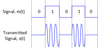
ON-OFF Keying (OOK)
FSK
In the article, Analogue modulation, we talked about frequency modulation or FM. By modulating the frequency of the radio wave sub-carrier with our message signal we can transmit analogue information such as a voice signal.
If instead of a continuous signal we use a bit stream, the result is a radio wave carrier with shifts in frequency corresponding to the "HIGH(1)" and "LOW(0)" level in our signal. This is known as Frequency Shift Keying or FSK.
Similar to FM, FSK is more resistant to noise than ASK since information is carried by frequency shifts instead of amplitude shifts. A further advantage of FSK is that since there are no amplitude changes, non-linear amplifiers that are more power efficient can be used. This makes FSK suitable for battery powered operation.
FSK can be implemented by switching 2 oscillators of different frequency in response to our digital signal. However without careful timing, phase discontinuities will be present extending the sidebands into neighbouring channels causing interference across the spectrum. It was discovered that by applying a modulation index of 0.5, phase continuity could be maintained and FSK schemes such as MSK (Minimum Shift Keying) and GFSK (Gaussian Frequency Shift Keying) could be realised.

FSK modulation with phase discontinuity (left) and phase continuity (right)
FSK finds its uses in telemetry, radiosondes on weather balloons, garage door openers etc. In some communication modems FSK can also be used to create audio tones (instead of using radio frequency) which can be used to send data across the telephone line. It is also used in amateur radio communication in the form of RTTY (Radio Teletype).
FSK variants
So far we have spoken about binary FSK where 2 frequencies are used to convey bit 1 or bit 0. By grouping 2 or more bits together we can form a symbol. For example, grouping 2 bits together means 4 symbols (00,01,10,11) and each symbol can be mapped to a frequency value. Thus higher order FSK such as 4-FSK can be realised and the result is that every symbol transition can now encode 2 bits.
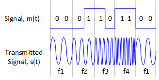
4-FSK
PSK
In the article, Analogue modulation, we talked about phase modulation or PM. By varying the phase of the radio wave carrier with our message signal we can transmit analogue information such as a voice signal.
If we use a bit stream instead of a continuous signal, the result is a radio wave carrier with shifts in phase corresponding to the "HIGH (1)" and "LOW (0)" level in our signal. This is known as Phase Shift Keying or PSK. The simplest PSK is BPSK (Binary Phase Shift Keying) where a single bit is mapped to one phase shift. For example, bit 0 can be 0 degrees and bit 1 can be 180 degrees phase shift.
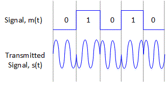
BPSK modulation
Like FSK, PSK is also not so impacted by noise and constant amplitude allows use of non-linear amplifiers. PSK and its large number of variants are used in a wide range of applications such as digital television (e.g. DVB-S2, ISDB), wireless LAN and BlueTooth. With the availability of PCs and soundcards, it is also used in amateur radio for transmitting text e.g. PSK31.
Practical implementation
In-phase and quadrature
In FSK and PSK, to design hardware that takes a radio wave carrier and precisely change its frequency and phase would be extremely difficult to design. In practice we use in-phase and quadrature modulation.
It can be mathematically shown that by taking 2 identical carriers that are 90 degrees out of phase with one another and amplitude modulating each one, we can modulate the radio wave carrier to contain any amplitude, frequency and phase. The below diagram shows how QPSK signal is created with the constellation diagram shown on the right.

In phase and Quadrature modulation (note that "-1" is LOW and "+1" is HIGH signal)
In the diagram every bit change corresponds to one of the I and Q signals being inverted. The result is we can shift the phase of our QPSK signal to each one of the symbols shown. Since there are 4 symbols to choose from, we can encode 2 bits at a time. This system can be extended to encode more bits into one symbol and increase the number of positions in our constellation diagram. The result is higher order systems such as 8-PSK or 16-PSK can be realised.

PSK modulation schemes
We can see that the 8-PSK will allow encoding of 3 bits per symbol - 3 times as many as BPSK. While this allows higher bit rates, the trade off is that in a noisy channel the symbols become more closely spaced and the receiver will have a harder time deciding which symbol was sent. The receiver will therefore demand higher SNR from such systems. For example a noisy QPSK signal might look like this:
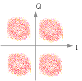
Noisy QPSK signal
Demodulation of FSK and PSK
We can see that the I and Q system used amplitude modulation to modulate each of the in-phase and quadrature carriers. We know that to demodulate amplitude modulated signals, we mix the incoming signal with the same carrier wave and then apply a low pass filter. Similarly if we can mix the received signal with the same in-phase and quadrature carrier signals used at the transmitter and low pass filter them we can recover the baseband I and Q. It is important that the locally generated in-phase and quadrature carriers used to demodulate the incoming signal have the same phase relationship as those used at the transmitter.
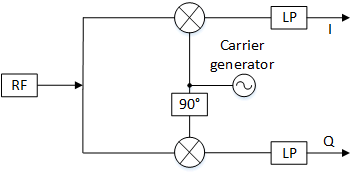
I and Q demodulation
Digital Quadrature Amplitude Modulation or QAM
It turns out that I and Q signals can be used to convey amplitude changes as well as frequency and phase. If we take a point anywhere in the constellation and measure its distance from the origin - this is the amplitude of our carrier wave. So I and Q can be used to receive AM transmissions.
The beauty of I and Q is we can combine phase and amplitude changes to map many points on the constellation diagram. These quadrature amplitude modulation systems can produce 8, 16, 64, 256 points.
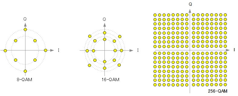
Quadrature Amplitude Modulation
