Superheterodyne receivers
Introduction
This article talks about the superheterodyne receiver and its principle of operation. Developed in the early 20th century, it was a vast improvement over the simple tuned radio frequency receiver (TRF) and is now one of the widely used techniques in radio today.
In this article, we talk about what the superheterodyne receiver is and discuss how it managed to overcome the problems found in early radios.
Tuned radio frequency receiver
For a radio receiver to operate, firstly there needs to be a method of gathering the radio waves and transporting the signals to the receiver circuitry. This usually consists of an antenna connected to the radio antenna input. Secondly a means of separating and isolating the signal you want which is achieved by some tuning process. Finally, a method of separating the transmitted signal (e.g. audio) from the carrier (referred to as demodulation and detection) that can be fed into headphones for listening, or into an amplifier for further amplification. We can illustrate the above with a tuned radio frequency receiver shown below.
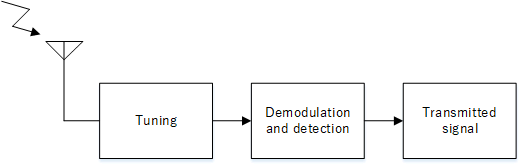
TRF block diagram
Early radios, known as crystal sets used a crystal (hence the name) to demodulate the radio signal and the output audio was fed directly to a piezoelectric crystal earphone with the energy in the radio waves being enough to drive it. Thus it did not need any batteries.
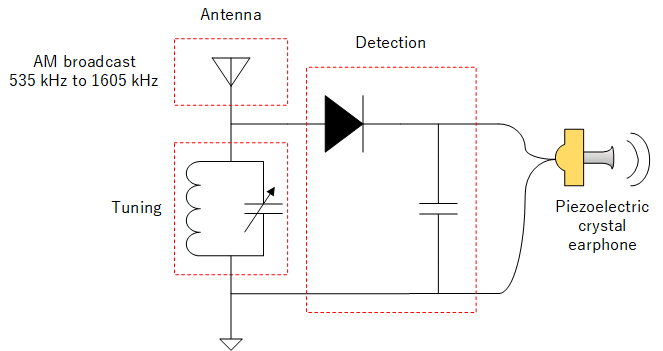
Crystal set
The tuning section contains a capacitor and a coil (a filter) to allow only the desired station to pass through to the detector. The tuning could be made variable by using a variable capacitor.
Whilst simple in design, there are disadvantages such as poor selectivity and sensitivity. Making a tuning filter to work uniformly across the frequency band and have narrow enough bandwidth to only let the wanted signal through is difficult. In the diagram below, the filter is tuneable across the whole band but adjacent signals are still partially able to get through the filter and be heard. In the past, as the number of broadcast signals increased over time, the increase in signal congestion only worsened the problem.
Regarding sensitivity, a filter that is wider than the wanted signal will raise the overall noise, reducing the ability of the receiver to pick up smaller signals.
Additionally, introducing further filtering and amplification stages all require each of them to be tuned to the incoming radio signal making the tuning process more difficult.
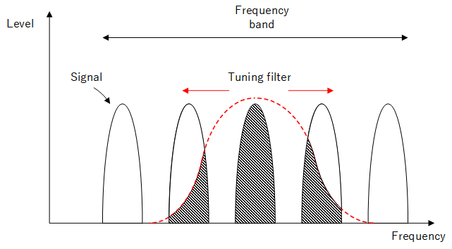
Tuning in a TRF receiver
Superheterodyne receiver
So now we have seen the shortcomings of the TRF, we shall see how the superheterodyne is able to overcome these issues.
Operation
We have seen that a TRF works by moving a tunable filter over the whole band. Allowing this and the other components to tune across the whole frequency band is difficult. If the radio only needed to tune a fixed frequency instead of all the frequencies in the whole band, then the TRF would be no problem. But tuning across the frequency band is desirable in most cases.
It should be obvious now that the TRF would not be the best approach to adequately tune across a range of frequencies. But also if we could process the radio signal at a single fixed frequency then all the RF circuitry can be designed around that frequency. A filter (and other RF stages) working at one frequency can have its bandwidth very well defined and would be easier to construct compared to the filter in the TRF. This would simplify the design process immensely.
So what can we do?
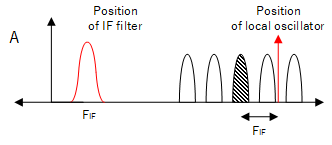
If the radio can shift the spectrum of the signals it receives, it can centre the wanted signal onto some common frequency. This frequency is called the intermediate frequency or IF.
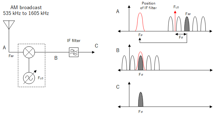
Superheterodyne tuning (lower side injection)
To shift the spectrum of radio signals, we can use a mixer and a local oscillator. The mixer outputs the product of the local oscillator and the antenna signals which contain the sum and difference of their frequencies, however we can just imagine that this moves the spectrum of received signals by an amount FLO until the wanted signal is centered on the IF frequency. Once the signal is centered there, it can be isolated by the IF filter. The formula for relating the IF frequency is:
$${F_{IF} }= F_{RF} - F_{LO} $$
To tune into another signal, we just change the value of FLO. For example, an AM broadcast from 535 to 1605 kHz with the IF being 455 kHz (typical IF in AM medium wave receivers) would mean that to receive a broadcast (FRF) at 1000 kHz, our local oscillator would need to be set to:
FLO = FRF - FIF = 1000 - 455 = 545 kHz
Upper side and lower side injection
So far we showed where the IF frequency is derived by setting the local oscillator frequency a distance FIF below the desired signal. This is lower side injection.
For upper side injection, the IF frequency is derived by setting the local oscillator frequency the same amount above the desired signal. The formula then becomes:
$${F_{IF} }= F_{LO} - F_{RF} $$
Upper side injection
Both techniques will output the same IF frequency. However, we will see the problem of image frequencies associated with the superheterodyne described in the following section, "Image frequency problem".
Advantages of the superheterodyne receiver
The advantages include improved selectivity as it is easier to design a filter with a narrower bandwidth at a lower frequency (due to the lower Q factor*). Also it is desirable to be able to adjust the filter bandwidth (to minimise noise) to suit the type of broadcast received. Such radios can be installed with switchable IF filters.
*Q factor is the ratio of the frequency to the filter bandwidth.
Another advantage is that tuning only requires changing local oscillator FLO. Once this is done, the following circuits only need to operate on the IF frequency.
Disadvantages of the superheterodyne receiver
Disadvantages of the superheterodyne include a more complex design compared to the TRF, but the main disadvantage is the generation of image frequencies.
Image frequency problem
Because the receiver works on the difference signal output by the mixer, there will be 2 different input frequencies that can generate the IF frequency. Wherever the local oscillator frequency is set to, there will be 2 values of FRF that will generate the same IF frequency:
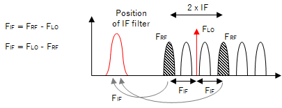
Image Frequencies
One value of FRF will be the signal we want that will pass through the IF filter. The other signal will also pass through the IF filter, but will be one we did not intend to create and this is referred to as the image frequency. As the receiver sees both as valid signals, there is no method to successfully remove the image frequency once it has entered the IF filter.
In general, the image frequency will be a distance 2xIF from the wanted signal with the FLO halfway in between.
Once the image frequency has passed through the IF filter, there is no way to remove it. So by prevention, we can attempt to filter out the image frequency before it can enter the mixer. We can do this by inserting a image rejection filter at the antenna side. It does not need to selectively pass a single frequency, but needs to attenuate the image frequency before it can enter the mixer. Since all frequencies in the band are images relative to each other, the filter would need to move during tuning. This is done by linking it electrically or mechanically to the local oscillator.
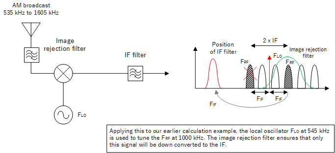
Image rejection
Choosing the intermediate frequency
The next question is what value to use as the IF frequency. It is a compromise between prevention of image frequency and selectivity.
We saw the problem of image frequencies earlier. At first glance, it seems we can solve this by moving the IF frequency to a higher value. Then filtering out the image frequency will be easier as it will lie further away (2 x IF). However, the problem of making IF filters to work at higher frequencies with the same bandwidth becomes difficult (high Q factor) and the result is poorer selectivity. Today, modern receivers can use crystal and ceramic filters allowing higher Q factors than LC circuits and also DSP filtering (in the case of software defined radios).
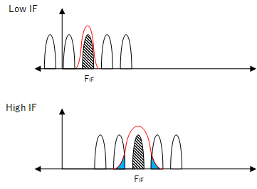
Using higher IF will lead to poorer selectivity
Double superheterodyne
In order to solve both image and selectivity issues, we can use 2 IF stages - a 1st IF and then a 2nd IF. The 1st IF can be used to reject, as much as possible, the image frequencies while the 2nd IF can be used to improve selectivity. For example, a radio with narrowband channels operating in the 434 MHz band can use 10.7 MHz as the 1st IF and 450 kHz as the 2nd IF.
Standard IF frequencies in use
The below table shows standard IF frequencies used by different systems.
| System | IF frequency | Bandwidth |
|---|---|---|
| Analogue television | 36 MHz | 6 MHz |
| FM broadcast | 10.7 MHz | 10 - 150 kHz |
| Domestic / HF | 455 - 500 kHz | 1 - 6 kHz |
Source: Betts, Alan G0HIQ and Hartley, Steve G0FUW "Advance! The Full Licence Manual", p64 Table 9A
