Filters and radio system design
Introduction
A filter is a device that permits certain signal frequencies to pass while blocking (or significantly attenuating) other frequencies.
Normally a filter is designed to isolate as much as possible, the correct frequencies for the radio. Or in the case of interference, a filter can try and block specific frequencies while leaving every other frequency intact (such filter is known as a notch filter).
Filters are present in audio and Hi-Fi systems handling signals in the DC-20 kHz range and there are filters operating into the MHz / GHz range for radio.
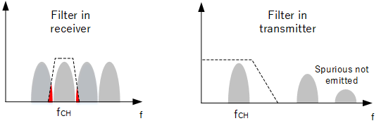
The radio spectrum is a limited resource containing many users transmitting in closely spaced channels, so filters ensure the reception of the wanted signal while suppressing as much as possible, all other signals. Similarly during transmission, filters ensure only in-band frequencies are transmitted to prevent interference to other users in the band or to any other bands.
Filtering examples
Filter types
Filters can be classified into 4 types:
-
- Low pass - passes all frequencies below f1
- Band pass - passes frequencies only from f1 to f2
- High pass - passes all frequencies above f1
- Band Stop - blocks all frequencies from f1 to f2.
- If f1 to f2 is very narrow, such filter is referred to as a notch filter.
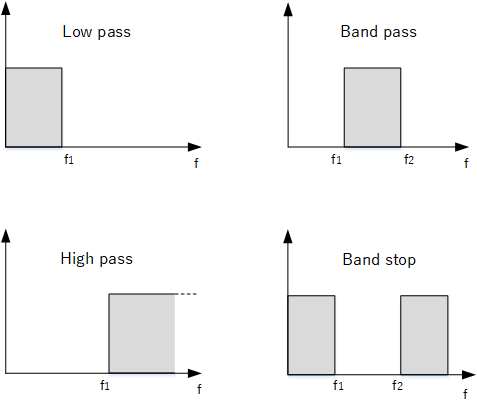
Filter types
Filter performance
The ideal characteristics of a filter would be as shown in the diagrams i.e. the frequency boundaries resemble a "brick wall" with the passband showing a flat response. The filter should have zero loss on the signals it is designed to pass, except outside the passband which it should completely block. However, we will find that real filters do not have ideal characteristics and their parameters have to be specified as follows (using low pass as an example):
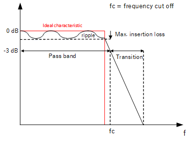
Low pass filter characteristics
Passband and transition
As we have mentioned, the passband of a filter refers to the range of frequencies the filter is allowed to pass. The frequency roll off is never instantaneous, so all filters contain varying degrees of transition width. By convention the passband bandwidth is taken where the level is -3 dB from the maximum value. Remember that in power terms, this is 0.5 (50%) of the maximum, but in amplitude terms (voltage) it corresponds to (0.707) 71% of the maximum.
Cut off frequency
The frequency value marking the beginning or end of the -3 dB passband width is known as the frequency cut off, fc. By knowing the frequencies we wish to pass, we can choose a filter with the correct frequency cut off.
Insertion loss and ripple
The insertion loss is the ratio of the filter's output level to the input level at any frequency. Commonly, it's used to describe the amount of loss in the passband as ideal filters should pass these frequencies with zero loss. In real filters, the passband response is not flat, but fluctuates creating varying degrees of insertion loss within the passband. This is known as the ripple - ideally we want a flat response so the ripple needs to minimised.
Filter selection
Since no perfect filter exists, improving the performance in one aspect usually means degradation in another. It is up to the engineer to compromise and decide which feature is the most important and select the filter accordingly.
Low pass filters in radio
Removal of harmonics
As mentioned previously, the transmitter chain can involve power amplifiers which can produce spurious frequencies, particularly harmonics which could be out of band and should not be transmitted. A low pass filter with a suitable cut off frequency can be used.
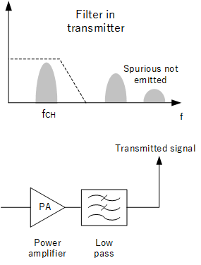
Removing out of band signals before transmission
Baseband processing
After the received signals are demodulated, the output will consist of baseband pulses containing our binary signal. The pulses need to have any voltage spikes or irregularities removed before being passed to the data slicer to prevent false readings (click here to find out more about data slicing).
In frequency terms, a pulse train contains its fundamental frequency and other higher frequency components caused by the spikes - by applying a low pass filter, we can remove the upper frequencies and suppress the spikes.
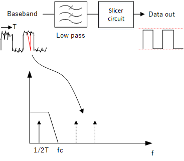
Removing transients (red) before data slicer
Band pass filters in radio
Out of band frequencies
A receiving antenna will mostly pick up all radio emissions from the environment - not just from the desired band of interest. Because permitted power levels can vary, it is possible that a strong signal from another band can enter the receiver and prevent reception of the signal we want. A filter at the input to the receiver can attenuate, as much as possible, any out of band signals. This feature is referred to as blocking.
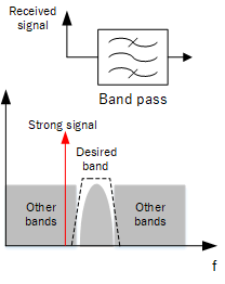
Isolating only the frequency band of interest
Preventing image frequencies
As has been discussed in the article "Superheterodyne receivers", a frequency below or above the signal we want to receive has a potential to be an image (depending if low or high side injection is used).
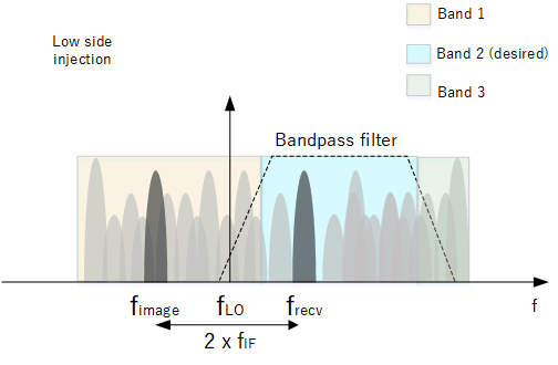 Without any filtering, a signal at the image frequency outside of our band may enter the receiver and also be demodulated allowing both signals to be heard. To prevent this, a bandpass filter can nearly remove all its influence.
Isolating the intermediate frequency
As has been discussed in the article "Superheterodyne receivers", the received signal is down converted to a fixed intermediate frequency (IF). Usually a filter whose pass band is equal to the channel bandwidth is used to isolate a single channel. As the IF is of a lower value and is fixed, it is not too difficult to find a filter to provide good channel selectivity.
Another point a filter helps with is receiver noise. Since this noise power is related to bandwidth and temperature (refer to the article, "Noise Figure"), a narrow filter can band limit our signal and lower the noise floor, improving signal to noise ratio.
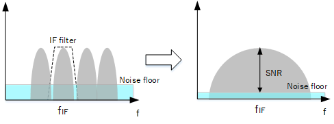
Narrow filter lowers noise floor
High pass filters in radio
It is possible to construct a bandpass filter by combining a low pass with a high pass filter.
As high pass filters block DC and low frequency signals, they can be found at the antenna terminal to stop DC from reaching the radio circuits caused by inappropriate installation of e.g. active antennas / amplifiers. The operation of radio circuits can be adversely affected by any DC bias. For low frequency signals such as electrostatic discharge, mains power hum, the filter is able to suppress such signals.
Band stop filters in radio
If there is a strong signal on a nearby frequency, the receiver's sensitivity to distant signals will be negatively affected. A band stop centered on the frequency (notch filter) at the antenna input can be used to prevent the interfering signal from entering the receiver's front end.
Another problem is saturation, in particular where the dynamic range is limited. For example, stronger FM broadcast signals can over power the receiver. A band stop filter covering the correct bandwidth can block the FM broadcast band frequencies.
During measurement of 12 dB SINAD (see article, "What is 12 dB SINAD"), the notch filter is used to remove the audio tone to allow measurement of only noise and distortion.
Filter types
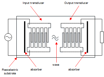
The below table is a summary of filter technologies.
Hardware filters vs software filter
Although filters based on physical components have been well established, there has been progress on implementing filters in software as part of DSP. Both methods have advantages and disadvantages.
All the filters discussed so far act in the analogue domain where the signals are transformed with physical components. However, a filter implemented in software operates in the digital domain - that is the filter takes in discrete (not continuous) values and transforms them mathematically to the desired output. Such filters have the advantage of being re-configurable, be updated in real time and generally free of the limitations imposed by the physical size of components. Such filters can be integrated amongst other radio functions and the entire architecture made more compact.
It does however require that an analogue signal is sampled meaning additional hardware is required. Also the performance of the filter will be dependent on the quality of the programming and the hardware resources available to it. Current consumption will increase with complexity making this implementation less desirable for those that wish to minimise current consumption as much as possible.
Another issue with digital filters is that of latency - programs need time to run and the delays may not be acceptable in some cases.
To go more in depth regarding software implementation of radio functions will be covered in a future article.
Conclusion
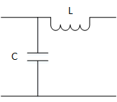
As we have seen, there are many types of filter complexity from simple passive LC all the way to software. As mentioned no filter has a perfect response, so it is up to the engineer to choose a filter type that is able to do the task adequately without adding unnecessary complexity. The location of the filter in the system chain is also important as well as the ability to mix difference types of filters according to function. Passive LC filters have the least performance, do not require power and are satisfactory enough to cover non-critical aspects of radio performance. Filtering related to communication quality and reliability demand more complex designs.
Software defined filters are becoming more common but they still lag behind traditional filters in areas such as latency and lack of dynamic range (the ability to handle strong signals). However the need to adapt to the ever increasing use of the radio spectrum means more advanced, configurable filters.
