Hamming and linear codes
Introduction
Radio communication in the field can be somewhat modelled as "a noisy communication channel" with interference from other signals, fading etc. , meaning the probability of reception is constantly influenced by emissions from other nearby equipment and location of obstructions. For analogue broadcasts such as voice and music, the signal to noise degradation can be heard as static on top of the voice or music which cannot be eliminated.
For transmission of data (such as a bit stream from a serial port), interference can cause a receiver to output e.g. a zero when a one was transmitted (a bit error). Data communication, unlike voice, cannot just be transmitted as it is. This is because a single bit error due to interference can lead to an incorrect action. Fortunately, through the use of various coding techniques bit errors can be detected and in some cases be identified and corrected.
Error detection vs Error correction
Depending on the severity of the communication conditions and the coding scheme used (of which there are many), a receiver can detect and in some cases be able to correct the bit errors. If a receiver can determine the presence of a bit error but cannot determine the position, this is purely error detection. In these cases, a receiver can reject the data or if the data is cyclic (repeating), wait for the next data. Or the receiver can ask the transmitter to re-send the data but it would be necessary to implement two way communication - increasing hardware complexity.
If the positions of the bit errors are known (and since a bit can only take a value of 0 and 1), the receiver can automatically recover the data by flipping the affected bits (error detection and error correction) and communication can continue with no breaks. The receiver does not need to ask for a re-send so no two way communication is necessary.
Whatever the coding scheme is used, it will always involve addition of redundant bits to the message which will lower the effective bit rate of the channel.
Block codes
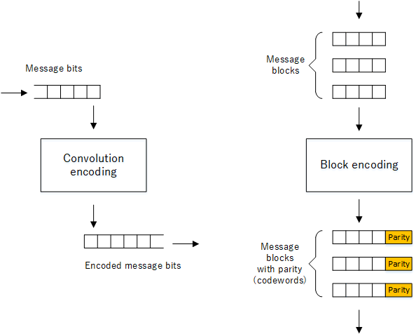
Coding schemes can be classified depending on how the message bits are encoded when adding redundancy. If the bits in the message are encoded individually, we have what we call convolution coding and the output will be a continuous stream of bits.

Convolution vs block encoding
However our focus for this article will be on block encoding, that is grouping message bits into blocks and encoding them as individual blocks. The output will be a series of codewords containing parity bits. During reception, the receiver can inspect the parity bits and determine if the received codeword contains errors.
Systematic codeword
When the parity bits are added but the original message bits remain in the codeword, these are referred to as systematic codewords. We will use systematic codewords as examples throughout this article.
Linear codewords
The result of block encoding means we that map all our messages to their corresponding codewords. So let us list all these codewords in a table as follows:
| Codeword table | |
|---|---|
| A | .. |
| .. | .. |
| .. | C |
| .. | .. |
| B | .. |
| .. | .. |
Imagine selecting any two codewords, A and B. Then perform the bitwise XOR addition on both and let us call the result C. For those unfamiliar with XOR addition, we can write it formally like this:
$$A \oplus B= C$$
*(for reminder of XOR addition: 0⊕0 = 0, 0⊕1 = 1, 1⊕0 = 1, 1⊕1 = 0, XORing even no. of ones produces zero and an odd no. of ones, a one)
For example if A = 0110 and B = 1100.
$$
\require{enclose}
\begin{array}{r}
0110 \\[-3pt]
\oplus\underline{1100}\\
1010
\end{array}
$$
Then C would be 1010. Then let's observe that C showed up as another codeword in the table. If we repeat the operation on all combinations of A and B codewords and the result was always another codeword in the table, then all of the codewords in the table are said to be linear. We will see how linear codewords make it easier to compute the minimum hamming distance, dmin
Hamming and matrix terms / notation
Matrices
To understand the example in this article, readers will need to be familiar with matrices.
Dimensions of a matrix
The dimensions of a matrix is expressed using height x width. For example:
$$
\text{A 3 x 2 matrix =}
\begin{bmatrix}
1 & 0 \\
1 & 0 \\
1 & 1 \\
\end{bmatrix}
$$
Identity matrix
An identity matrix (In) is a square matrix that has all diagonal ones and zero in other places. For example:
$$
I_1 =
\begin{bmatrix}
1 \\
\end{bmatrix}
$$
$$
I_2 =
\begin{bmatrix}
1 & 0 \\
0 & 1 \\
\end{bmatrix}
$$
$$
I_3 =
\begin{bmatrix}
1 & 0 & 0 \\
0 & 1 & 0 \\
0 & 0 & 1 \\
\end{bmatrix}
$$
A matrix multiplied (see Matrix multiplication below) with an identity matrix - leaves the source matrix unchanged. It is analogous to multiplying a number by one.
Transposition
Transposing a matrix means to swap the rows and columns. The matrix that has been transposed is written as MT. For example:
$$
M =
\begin{bmatrix}
\color{red}{1} & \color{red}{0} & \color{red}{0} \\
1 & 1 & 0 \\
0 & 1 & 1 \\
\end{bmatrix}
$$
$$
M^T =
\begin{bmatrix}
\color{red}{1} & 1 & 0 \\
\color{red}{0} & 1 & 1 \\
\color{red}{0} & 0 & 1 \\
\end{bmatrix}
$$
Matrix multiplication
\(
\begin{bmatrix}
\color{red}{0} & \color{red}{1} & \color{red}{0} \\
\end{bmatrix}
\begin{bmatrix}
\color{green}{0} & 0 & 1 \\
\color{green}{1} & 1 & 0 \\
\color{green}{1} & 0 & 0 \\
\end{bmatrix}
=
\begin{bmatrix}
(\color{red}{0}×\color{green}{0})\oplus(\color{red}{1}×\color{green}{1})\oplus(\color{red}{0}×\color{green}{1}) & 1 & 0 \\
\end{bmatrix}
=
\begin{bmatrix}
1 & 1 & 0 \\
\end{bmatrix}
\)
For matrix multiplication, multiply the row in the first matrix with the column in the second matrix. Then combine using XOR addition to produce the first member in the result. Then move to the second column in the second matrix and repeat.
Codeword length (n)
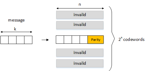
When the message blocks are transformed into codewords, each codeword will be a fixed length, n bits. Then the number of possible codewords will be 2n.
Message length (k)
Each message will be of length k bits. Hopefully it is clear that we will need to allocate 2k out of a possible 2n codewords to create our valid codeword table. The unallocated codewords, equal to 2n - 2k will be deemed as invalid codewords if the receiver sees them.

Mapping messages to codewords
Generator matrix (G)
To convert our message into a linear codeword (c), we multiply our message(m) with a generator matrix (G) as follows:
$$
c = \begin{bmatrix} m_1 & m_2 & . & m_k \end{bmatrix} \overbrace{\begin{bmatrix} I_k & | & P_{k×(n-k)}\\ \end{bmatrix}}^{G}
$$
You can see that the generator matrix contains an identity matrix (I) and a parity matrix (P). The identity matrix ensures that m1 to mk of the source message are preserved (systematic) in the final codeword while the parity matrix (P) adds the parity bits.
Parity check matrix (H) and Syndrome (s)
The parity check matrix (H) has the form:
$$
H = \begin{bmatrix} P^T_{(n-k) \times k} & | & I_{(n-k)}\\ \end{bmatrix}
$$
The receiver multiplies the received codeword (c) with the transposed parity check matrix - that is HT to give us the syndrome (s)
$$
s = \begin{bmatrix} c_1&c_2&.&c_n\\ \end{bmatrix} H^T
$$
If the syndrome vector returns all-zero entries, the received codeword is valid.
Hamming distance (dH)
The Hamming distance (dH) represents the number of bit changes when moving from one codeword to another. For example going from codeword 010 to 111 would involve the following bit changes.
$$
\begin{bmatrix}0 & 1 & 0 \\\end{bmatrix}\rightarrow\begin{bmatrix}\color{red}{1} & 1 & 0 \\\end{bmatrix}\rightarrow\begin{bmatrix}1 & 1 & \color{red}{1} \\\end{bmatrix}
$$
The above example requires 2 steps which is equal to a dH of 2.
More formally stated, the Hamming distance (dH) is equal to the number of non-zero digits after XOR'ing both codewords into the operation:
$$
\require{enclose}
\begin{array}{r}
010 \\[-3pt]
\oplus\underline{111}\\
101 \\
\end{array}
$$
There are 2 non-zero digits meaning dH is 2.
Hamming weight
The Hamming weight is the number of non-zero entries in a codeword. For example, the Hamming weight of "101" is 2.
Minimum Hamming distance (dmin)
The minimum Hamming distance (dmin) is the smallest Hamming distance that exists after iterating over all possible pairs of codewords. If the codewords are linear, then the minimum Hamming distance can be easily seen by looking at the codeword with the smallest Hamming weight (excluding those with all zero entries).
As we shall see, by knowing the minimum Hamming distance, it is possible to know the number of detectable errors and also determine the number of errors that can be corrected.
Hamming (7,4) example
When implementing Hamming(n,k), we need to specify n and k where "n" is the codeword length and "k" is the length of the source message. These terms were explained earlier above.
So we want to send the message with k = 4 bits, for example 1011 with the codeword length (n) set to 7. We use a generator matrix G as follows:
$$
G =
\begin{bmatrix}
1 & 0 & 0 & 0 & 1 & 1 & 0\\
0 & 1 & 0 & 0 & 1 & 0 & 1\\
0 & 0 & 1 & 0 & 0 & 1 & 1\\
0 & 0 & 0 & 1 & 1 & 1 & 1\\
\end{bmatrix}
$$
We multiply our message with G to create our codeword. For easy visualisation, the parity operators have been coloured in green.
$$
\begin{bmatrix}
1 & 0 & 1 & 1\\
\end{bmatrix}
\begin{bmatrix}
1 & 0 & 0 & 0 & \color{lime}{1} & \color{lime}{1} & \color{lime}{0}\\
0 & 1 & 0 & 0 & \color{lime}{1} & \color{lime}{0} & \color{lime}{1}\\
0 & 0 & 1 & 0 & \color{lime}{0} & \color{lime}{1} & \color{lime}{1}\\
0 & 0 & 0 & 1 & \color{lime}{1} & \color{lime}{1} & \color{lime}{1}\\
\end{bmatrix}
=
\begin{bmatrix}
1 & 0 & 1 & 1 & 0 & 1 & 0\\
\end{bmatrix}
$$
For the receiver, let's say that the received codeword(c) was 1000101 (instead of the transmitted codeword 1011010). As explained, the parity check matrix (H) is composed of the transposed parity bits from the generator matrix (shown in green) with the identity matrix (In-k).$$
H =
\begin{bmatrix}
\color{lime}{1} & \color{lime}{1} & \color{lime}{0} & \color{lime}{1} & 1 & 0 & 0\\
\color{lime}{1} & \color{lime}{0} & \color{lime}{1} & \color{lime}{1} & 0 & 1 & 0\\
\color{lime}{0} & \color{lime}{1} & \color{lime}{1} & \color{lime}{1} & 0 & 0 & 1\\
\end{bmatrix}
$$
To obtain the syndrome, we multiply our received message with the transposed parity check matrix (HT):
$$
s =
\begin{bmatrix}
1 & 0 & 0 & 0 & 1 & 0 & 1\\
\end{bmatrix}
\overbrace{
\begin{bmatrix}
1 & 1 & 0 \\
1 & 0 & 1 \\
0 & 1 & 1 \\
1 & 1 & 1 \\
1 & 0 & 0 \\
0 & 1 & 0 \\
0 & 0 & 1 \\
\end{bmatrix}
}^{H^T}
=
\begin{bmatrix}
0 & 1 & 1 \\
\end{bmatrix}
$$
If the syndrome returns all zero entries, the received codeword is valid. Since our syndrome is not all zeros, our received codeword is not valid.
So why use linear codewords?
So far we have discussed the use of linear codewords and how to create them through a generator matrix. But why bother using linear codes?
Initially you may think a lookup table containing all the codewords for the k messages would be sufficient. However, this is not a very efficient method and requires memory space to store 2k codewords.
By using linear codewords, we only need to know k codewords to act as a seed for generating all the 2k codewords. Referring to the generator matrix in our Hamming(7,4) example:
$$
G =
\begin{bmatrix}
1 & 0 & 0 & 0 & 1 & 1 & 0\\
0 & 1 & 0 & 0 & 1 & 0 & 1\\
0 & 0 & 1 & 0 & 0 & 1 & 1\\
0 & 0 & 0 & 1 & 1 & 1 & 1\\
\end{bmatrix}
$$
only the 4 highlighted values in the table below need to be stored into the generator matrix, which multiplied with the message can re-produce all 16 codewords in the table.
| 24 (16 codewords) for the Hamming(7,4) example. | |
|---|---|
| 1000110 | .. |
| .. | .. |
| .. | .. |
| 0100101 | .. |
| .. | 0010011 |
| .. | .. |
| .. | .. |
| .. | 0001111 |
Graphical interpretation of Hamming
So far we have discussed the mathematical computation to generate codewords. It is also easy to see the minimum Hamming distance when the codewords are linear by looking for the codeword with the lowest Hamming weight.
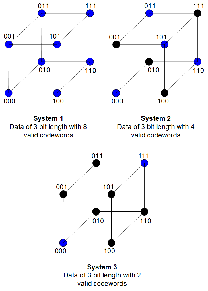
Another method of illustrating Hamming is by representing codewords on a space diagram. For example:

Example of Hamming codes
The dots represent codewords where each codeword is one Hamming distance from its neighbour. Only the blue dots represent valid codewords with the rest as being invalid. In system 1, all codewords in the space are valid (Hamming distance of one), so we have more codewords available to use. But there is no error detection ability as each shift results in another valid codeword. In system 3, we are limited to only 2 codewords, but the ability to detect/correct errors will be higher.
Error correction and detection for various minimum Hamming distances (dmin)
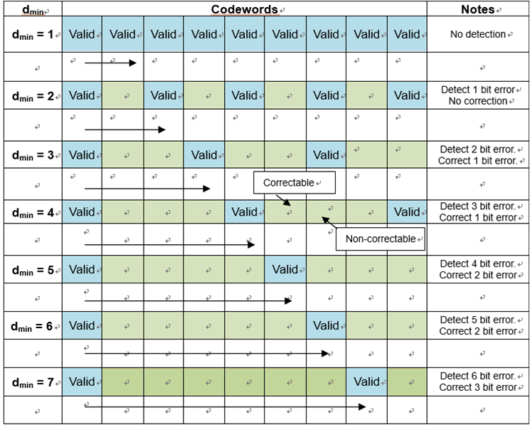
If we list all the codewords in a table in order of their minimum Hamming distances, you can see the amount of errors that can be detected and corrected.

Codewords in order of minimum Hamming distance
The number of correctable errors will always be less than the number of detectable errors and are related by the following formulas:
$$
\text{Detectable errors: }E_d = d_{min} - 1
$$
$$
\text{Correctable errors: }E_c = (d_{min} - 1)/2
$$
*For correctable errors, if the result is a fraction - round downwards
Conclusion
Error detection and correction encompasses many techniques - to describe all of them exhaustively is beyond the scope of this article. Broadly speaking, they can be classified under block or convolution coding.
The decision on the type of error detection and correction required for satisfactory communication will depend on the application requirements. As with engineering, there are costs if you want to implement error detection and correction in your communication.
Lower effective bit rate: Extra bits are attached to the source data meaning it would take longer to transmit the information under the same bandwidth constraint.
Two way communication: When the receiver detects errors, there is an option to request a re-send which would necessitate the implementation of a two way link. This increases the hardware complexity. However if the transmissions are cyclic, we can discard erroneous packets without requesting a re-send.
Delay: When the receiver checks the data for errors, it has to perform calculations and if applicable, correct any bits that are in error. Each calculation step takes time to execute and the delay introduced may become significant. The delay can only increase, if more calculations are required. If transmissions are cyclic, it maybe quicker to detect and discard the erroneous data rather than correct it.
