Connecting your antenna to the radio module
How important is the antenna in a radio system?
Sometimes engineers looking to develop radio systems place a lot of emphasis on the features of the radio and as a result the antenna aspect is overlooked. As the antenna is responsible for the emission and reception of radio waves, no radio will work optimally if the signal presented to it is of poor quality.
After studying this article, engineers should be able to install their antenna in a way that ensures best communication performance.
Installing the radio and antenna inside the enclosure
Both the radio and the antenna are incorporated into the enclosure. The antenna is directly installed on or near to the same PCB as the radio module without the need for any lengthy coaxial cable, requiring only a short length of copper feed or in some cases, having the antenna etched into the PCB itself (refer to 2.4 GHz Telecommand Module, NK-2.4Y example below).
Since the antenna is confined to the enclosure, the product can be made portable and held easily in the hand. The antenna is protected from any impact damage / weather and there is little or no signal loss due to any cable.
Being inside the enclosure, the antenna performance can be compromised due to the difficulty of fitting a full size antenna in a small space and its close proximity to other components which can detune the antenna. As frequency increases, antennas become smaller and installing it inside the enclosure becomes more feasible. For example, the wavelength at 2.4 GHz is 12cm - the antenna is likely to fit into a handheld unit. But to do the same for 434 MHz we get 70cm - not so feasible. In all cases however, the enclosure must allow radio waves to pass through it and the enclosure cannot be metal. With the antenna inside the enclosure (unless there is a connection to use an optional antenna), the user cannot change the antenna or extend it away from the unit.
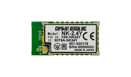
2.4 GHz Telecommand Module, NK-2.4Y integrating both pattern antenna and radio on the PCB.
Antenna mounted on the enclosure
There is the option to install the antenna on the enclosure itself. We see this on handheld mobile radios that use either fixed or retractable antennas. Radios may have a threaded connector on the enclosure allowing antennas to be interchangeable, as well as the option of extending the location of the antenna using a coaxial extension cable.
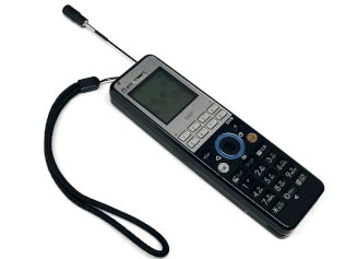
Digital cordless phone with retractable antenna
With the antenna outside of the enclosure, they can be more appropriately sized and communication improved. The enclosure can be made of any material as the radio waves are unaffected by it. When using 1/4 lambda antenna, a ground plane can be incorporated into the internal PCB, but a metallic enclosure can also act as a ground plane if so required.
Unlike the internal antenna, an external antenna can be susceptible to impact damage.
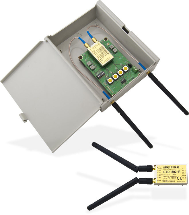
External connectors on the DSSS Low Power Radio Transceiver, STD-502-R with extension cable and flange connector (CBL-RPSMA-02-R) for mounting on the customer enclosure
Installing antennas in a remote location
This involves placing the antenna away from the radio and in a location where maximum line of sight communication can be achieved. A coaxial extension cable is necessary to transport the signals to and from the antenna. The cable should be selected so as not to have too high loss on the signal.
This method can be used to clear the antennas of obstructions such as buildings and trees in order to achieve line of sight communication. Suitable antennas can be chosen and installed for fixed point to point communication. The extra height can increase communication range as well as reduce the risk of interference to and from ground equipment.
As well as line of sight, these antennas whether they are internal / external to the enclosure or remotely placed should meet the Fresnel zone and antenna height pitch criterion. Their calculation tools can be found at the following pages:
If installed outside, the antenna and cable are exposed to the environment and significant weather proofing is required as described below.
Weather proofing and installation
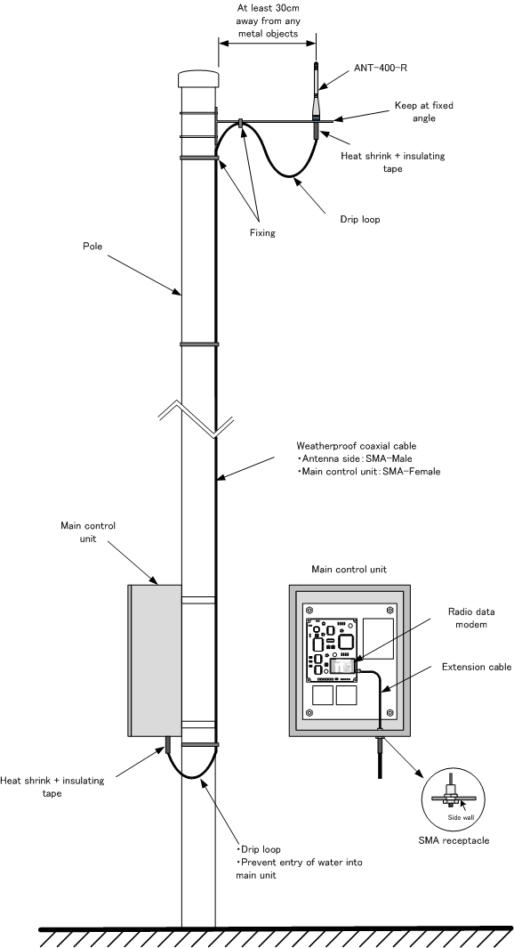
Antenna placed in the optimum location for communication.
To prevent water damage due to rain, we can install waterproofing tape, heat shrink or cable glands around connectors. Drip loops around cables can prevent water seeping into the antenna and enclosure. If the installation is within a building, then no weatherproofing is required. But certain building materials (e.g. concrete) can attenuate radio signals especially if wet.
The coaxial cable can be protected by conduit, electrical sheathing and attached to the support mast using suitable fixtures / clips. For bending cable around obstacles, care should be taken not to exceed its turn radius or apply any unnecessary strain.
Condensation prevention
If the enclosure is sealed, the temperature fluctuations can increase the humidity inside. So enclosures should have ventilation to allow circulation of air. However there is a risk that moisture carried by the air can condense on sensitive components causing transmission and reception problems in the radio. As a preventive measure, any ventilation holes should be covered with a filter to allow air to pass but not water.
Lightning protection
Regarding thunderstorms, the antenna can be a potential contact for lightning strikes especially if the antenna is the highest thing around you. If thunderstorms are a frequent reoccurrence in your location, it is recommended to install protective measures to prevent damage to equipment and property. Below are some points to consider.
Selecting the location
Before installing the antenna, it is worth reviewing the environment to see what other objects (trees, buildings etc.) are present. Lightning will try to find the shortest path to ground, so having the antenna as the highest structure around will increase the risk. One way is to reduce the height of the antenna or install it in a more sheltered location such as on a wall beneath the roof line.
Installing lightning arresters
Lightning arrestors are installed in-line into the coaxial cable between antenna and the building which will divert any excess voltage to ground. The arrester outer shell has a terminal for attaching a wire going to a ground point. It does not affect the RF signals flowing between the antenna and radio.
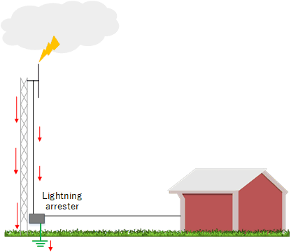
The voltage surge through the cable is diverted by the arrester to ground keeping it away from the building
Grounded antenna vs. non-grounded antenna
If voltages find their way onto the antenna due to lightning strike, charges will accumulate unless a way can be found of discharging them to ground. For antennas that do not use a ground plane (e.g. sleeve antenna or dipole), there is no ground to drain away any excess charge during a thunderstorm. Such antennas would have to be supplemented by something such as a lightning arrester.
For antennas with ground plane, refer to "Monopole antennas" in "Antenna types and parameters"
Induced currents from lightning
If lightning strikes a utility line servicing a residential/industrial area, high currents can be generated that may distribute themselves over a wide area. These currents will try and find a route to ground anywhere possible - not just through the utility pole ground. Measures such as the installation of an isolation transformer at the supply can prevent these currents from entering the radio.
Installation components
Antenna
Information on selecting the antenna on the basis of its electrical parameters can be found in this article "Antenna types and parameters".
For the physical aspects, various antenna manufacturers will provide for example:
- Dimensions
- IP ratings
- Antenna weight
- Antenna loading due to wind (dependent on the antenna's aerodynamics)
- Connector type
- Maximum power handling (amount of input power that the antenna can physically handle during transmission).
The last point is not of concern if the antenna is receive only.
Coaxial cable
The coaxial cable is responsible for transporting the signals between the antenna and the radio. The main parameters to consider are characteristic impedance (see article "Impedance and Standing wave ratio") and cable loss (in dB/m). A thicker cable will have lower loss but less freedom of movement when installing due to greater stiffness and larger bend radius as well as higher cost (that includes the materials used to manufacture the cable).
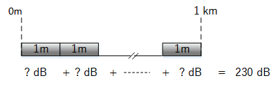
Cable losses are mentioned in link budgets (see article "Link budget"), a feasibility model for communication between transmitter and receiver. It is included when formulating the link budget. For example the RG-58A/U cable type, the loss is 230 dB/km at 200 MHz. The loss per metre can be calculated very easily when these values are given in dB.
Values can be added when expressed in dB.
Using 10m cable at this frequency, its loss would be:
230 / 1000 = 0.23 dB/m
0.23 x 10 = 2.3 dB loss between transmitter and antenna. This corresponds to 40% of the signal lost on the way to the antenna.
Connectors
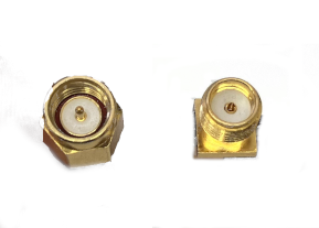
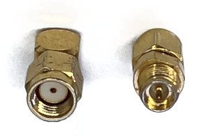
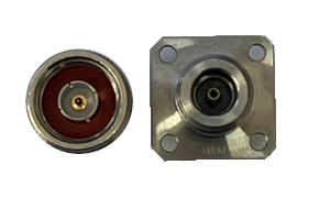
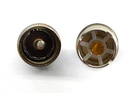
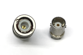
There are various connectors that are used for connecting radio equipment. SMA uses robust connections and are commonly found at higher frequencies. They are configured as "normal" and "reverse" with the centre pin swapped for the reverse configuration. Connectors such as UHF are commonly used in amateur radio equipment due to their robustness. Type-N is more costly than UHF, but because of its higher frequency handling capabilities, they can be found in e.g. RF measuring equipment.
SMA
| Normal SMA (Male and Female) | Reverse SMA (Male and Female) |
|---|---|
 |
 |
Others
| Type-N | UHF | BNC |
|---|---|---|
 |
 |
 |
