Requirements for transparent interface
What exactly is "Transparent interface"?
Normally referred to as "raw data handling", Circuit Design uses the term "transparent" when describing this type of interface.
A radio module that is "transparent" does not contain any extra circuitry to handle your data and only uses your input signal to modulate a carrier. Similarly, during reception, the signal from the demodulation and threshold detection is output directly. In other words, it is just sending and receiving data "as it is".
By this, it is easy to assume that you can just replace a wired connection (e.g. RS232) with a wireless link. However signal propagation in space has different characteristics which must be taken into account and so it is necessary for the engineer to properly format the data before transmitting.
General concept of transparent interface.
For transparent interface, there is no data handling by the module and the engineer has more control of the radio part. The engineer can format the data as desired leading to e.g. use with existing communication equipment, optimisation of the protocol for the application, scaling the protocol for the amount of data etc. All this allows higher levels of customisation and experimentation by the engineer. The lack of any data handling means that it is possible for such modules to use data rates other than the standard. In contrast, a module that incorporates an internal buffering system will tend to only support standard data rates.
The main requirement is that, for transparent interface there needs to be a way of detecting the frame (header) in order to begin data reception and the engineer has to incorporate these extra functions into the program.
Hardware requirements for transparent interface
An example configuration for transparent interface
There needs to be data flow from the CPU to the radio module (it will be bi-directional if the module is a transceiver). The pins would need to be configured for DI and DO.
Adding communication protocol - an example
Using transparent interface means the engineer has the freedom to format the packet as desired before transmission. Below is a general example of how a formatted packet might appear with some explanations.
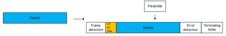
A formatted packet for radio communication
Preamble
Before transmitting the formatted packet, a short clocking signal called a preamble is sent for a period of time (e.g. just over several ms) to the other module. The purpose is to stabilise its receiving circuits for reception.
If the packet transmission is continuous (cyclic), the preamble is only sent at the beginning of a new transmission.
Frame detection
Because of the preamble, the target module is ready to demodulate and output the signal for the formatted packet from the DO pin. However, up to this point all the CPU sees is noise on the DO pin meaning that the CPU does not know where to begin reception. For this, the engineer needs to devise a method to allow the CPU to sense the arrival of new packet data. There are various methods e.g. the CPU can monitor the DO pin and begin reception of the new packet when it sees a certain signal transition.
Once the CPU has detected the signal transition, it can start receiving and analysing the packet. For secure communication, the engineer is free to include extra information with the packet as suggested below:
Channel information
If other equipment is operating on a similar channel, there is the possibility that it will receive the same signal (if the signal is strong enough to over power it). If the frequency channel information is included in the packet, such packets can be ignored.
ID
Including ID information allows "pairing" i.e. you can perform 1:N or N:1 communication.
Data size
The size of the packet in bytes. Knowing this the CPU can determine if all the data has been received.
Error detection / correction
Including error detection bits in the packet can determine if bit errors have occurred during reception. Sophisticated error detection mechanisms can even allow automatic correction of bit errors.
Receiving the packet
Bytes in the packet can be processed and analysed in real time or done after complete reception of the packet. Although for process optimisation, it is necessary to process in real time.
Detection of frame
As mentioned, there are various ways for the CPU to realise an incoming packet. Then should it prepare the serial hardware for receiving. It should not be processing any other signal (such as the preamble or noise). Should packet reception stop midway because of communication loss, a time out proceedure can be implemented in preparation to receive the next frame.
Once the packet has been received and processed, the serial receive can be disabled until the detection of the next frame.
Channel and ID check
If other equipment on a similar channel can demodulate and output the packet by accident, it will be able to realise this by comparing the channel information with its own channel setting. Following this the appropriate action can be taken e.g. discard the packet. Similarly, if the ID information does not match with the equipment ID (used when communicating N:1 or 1:N), the system can ignore the packet.
Data size
A counter in the CPU program can count the bytes. It can then know if all the bytes have been received.
Error detection / correction
If errors have been confirmed, the system can either correct them or if not, the equipment can either request a retransmission or discard the packet.
User data output
Once the transmission integrity is confirmed, the user data in the packet can be isolated.
