Third order intermodulation / Channel planning
What is the intermodulation problem?
Intermodulation is a phenomenon where spurious signals (intermodulation products) appear in the receiver during reception of the wanted signal. This is a result of the non-linear nature of the components used. While most intermodulation products can be filtered out, problems occur when they appear in band. In such cases, these intermodulation products would be impossible to filter out.
In a multichannel radio system, problems can occur if the intermodulation products spill onto the channel of interest, meaning the receiver will have difficulty receiving signals on such channels. Therefore it is necessary to carefully create a channel plan to prevent such interference.
How concerned should I be about the intermodulation problem?
If your application involves several transmitters and receivers close to each other and operating together in the same area, it is advised to read this article and create a channel plan as explained below. If a channel plan becomes necessary the number of useable channels will be much less than the channels offered.
2nd order intermodulation
A type of unwanted signal are the harmonics. These are integer multiples of the fundamental frequency f such as 2f, 3f, 4f etc. This is normally not a problem as at higher frequencies these harmonics gradually decrease in amplitude. Another type of unwanted signal is the sum and difference of two input frequencies, f1 and f2 (f1 and f2 are known as 1st order intermodulation products). These 2 frequencies mix together producing f1 + f2 and f2 - f1. The frequencies 2f1, 2f2, f1 + f2 and f2 - f1 are called the 2nd order intermodulation products.
1st and 2nd order intermodulation products
3rd order intermodulation
So far we have covered 1st and 2nd order intermodulation products. Unfortunately it does not stop there.
If we take the 2nd order products, 2f1 and 2f2 and mix them with the 1st order products, f1 and f2 we will get new frequencies, 2 of which are:
- 2f1 - f2
- 2f2 - f1
These are known as the 3rd order intermodulation products. The 3rd order products are the most problematic as they will appear near the input frequencies, f1 and f2 (shown in grey) and impossible to filter out.
3rd order intermodulation shown in red
If the frequencies, f1 and f2 corresponded to communication channels, then the channels occupied by the 3rd order products will be unavailable for normal communication (they would interfere with actual signals on those channels). For example in the diagram above if CH01 and CH02 are the input frequencies, the channels CH00 and CH03 cannot be used.
Demonstration of 3rd order intermodulation
We can use a spectrum analyser to show 3rd order intermodulation. The image from the spectrum analyser below shows signals on channels 2 and 3, 863.2500 MHz and 863.3750 MHz (center peaks) emitted by 2 Circuit Design audio transmitter modules, WA-TX-03S.
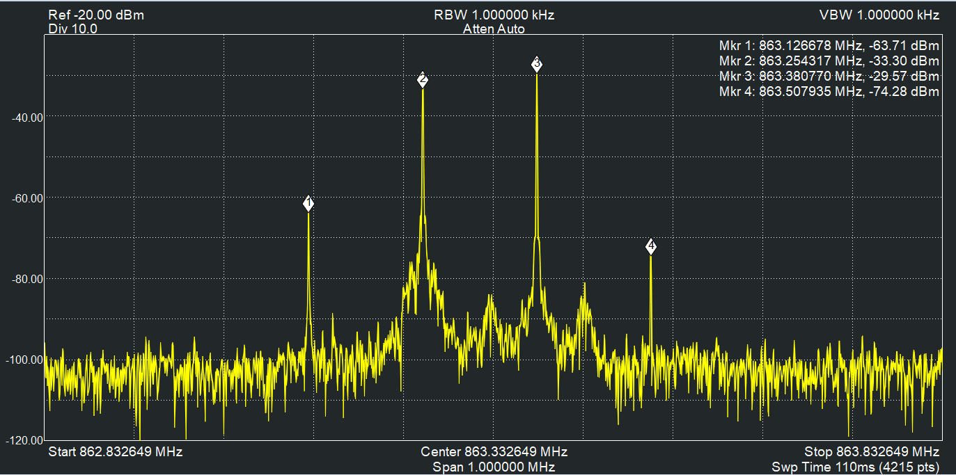
Signals emitted by 2 WA-TX-03S audio modules.
We can see the 2 extra frequencies (3rd order products) occurring at approximately 863.1250 (channel 1) and 863.5000 MHz (channel 4). These occur because of the close spacing of the transmitters causing their signals to interfere with each other.
Likewise, if the transmitters become too close to the receiver, we would also get a similar result. In both cases, these unwanted signals lie on the adjacent channels so they should not be used by other receivers.
Calculation tool to avoid the problem of third order intermodulation
Circuit Design has a tool at www.cdt21.com/technical_tools/channel-planning/ that calculates when the 3rd order intermodulation will occur. It can tell the user which channels to use and which not to use.
3rd order intermodulation tool by Circuit Design
Creating a channel plan
- After creating the channel table, we can select some channels to start with (in green). When a channel entry becomes yellow, it means this channel cannot be used.

Selecting channels in green. Yellow means forbidden channel
- If the forbidden channel is selected, channels with 3rd order intermodulation interference will be indicated in red. By avoiding this, a channel plan can be created without 3rd order intermodulation occurring.
Red means 3rd order intermodulation interference occurs on these channels
Conclusion
We can summarise the points regarding 3rd order intermodulation:
- The 3rd order intermodulation should be considered when multiple channels are used in the same area simultaneously.
- The user cannot just assign channels randomly.
- Not every channel can be used (the number of useable channels will be much less than offered by the radio module). For example using the tool to create a channel plan for Circuit Design's 2.4 GHz transceiver module, STD-503, only allows 9 channels out of the 77 to be used.
Circuit Design's 2.4 GHz transceiver module, STD-503 channel plan
However, the calculation tool describes the worst case scenario if 3rd order intermodulation is to be completely avoided. In actuality and taking the near-far phenomenon into account, the impact of 3rd order intermodulation can be ignored if transmitters and receivers are appropriately spaced. For example, avoid receivers being in reception range of multiple transmitters to prevent interference.
It is also recommended to increase the separation between channels as much as possible.