MU series - Evaluation program
Introduction
The MU-4-434 radio modem already comes equipped with various commands allowing users a convenient method to use the modem. In addition Circuit Design provides an evaluation program for the MU-4-434 that, when used in conjunction with the modem, can perform air monitoring and packet communication tests.
This article introduces the evaluation program for the MU-4-434 modem and MU-2-R, explaining in particular the air monitor and packet communication tests and how they can be used as a visual aid in helping engineers understand how easily communication conditions can fluctuate. By connecting a test board to the PC, the results can be viewed in real time.
Preparation
Necessary items
- 2 x either RS232 Interface Board or USB Interface Board (it is recommended to use the RS232 Interface Board to minimise interference from noise)
- Cable to connect the interface board to the PC.
- Windows PC is required, preferably a notebook PC.
- Evaluation program, MU2-ESP
Other requirements: ensure that you use the appropriate antenna and any necessary fixtures.
Installation of evaluation program
Details on the evaluation program can be found at Circuit Design here.
Starting the evaluation program
Before starting the evaluation program, ensure that the interface board and module are connected to the PC. When the folder with the application is opened, there will be an .exe with the name, "MU2_ESPe.exe". Click on its icon ![]() to start the evaluation program.
to start the evaluation program.
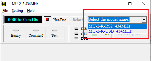
Once opened, select the relevant module / interface type used in the drop down list.
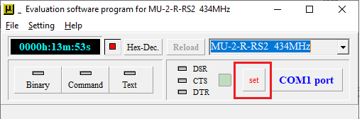
Underneath the model selection drop down list, click the "set" button.
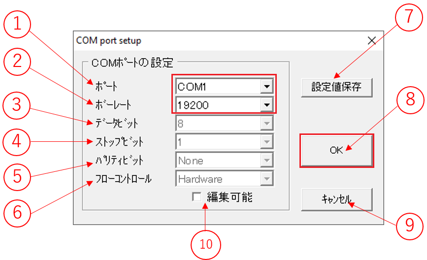
The COM port setup dialog box shows the available COM ports on your PC and the baud rate. By default, these are the only 2 parameters that need to be set.
Items in the COM port setup dialog box:
- COM Port
- Baud rate
- Bit length
- Stop bit
- Parity bit
- Flow control
- Save setting values
- Accept and return to main screen
- Cancel and return to main screen
- Edit settings enable (allows items 3 to 6 to be edited)
Setting up the COM port
In the COM port setup, the software needs to be looking at the correct COM port. Select the COM port using the dropdown list (1). Similarly, then select the correct baud rate (2) for the module (usually 19,200 bps). Leave the other settings alone and press OK button (8).
Confirmation using RSSI (Received Signal Strength Indication)
Frequency domain
During module installation and communication testing it is important to see the noise level or see the channels that are vacant. Even if the module has good RF performance, a high noise floor / interference from other devices using the same channel can cause errors in communication. The evaluation program features an "Air Monitor" function that allows you to monitor and confirm the frequency channels used in your area.
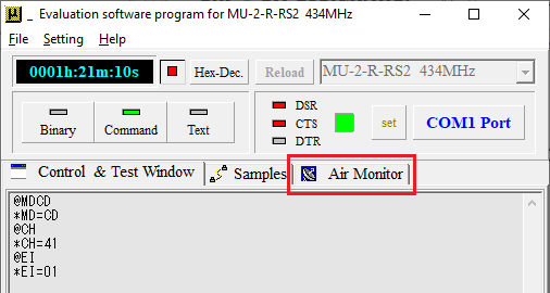
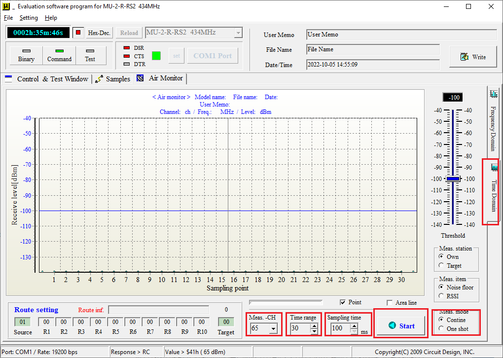
To begin confirmation of channel usage in your area, click on the "Start" button in the "Air Monitor" tab.
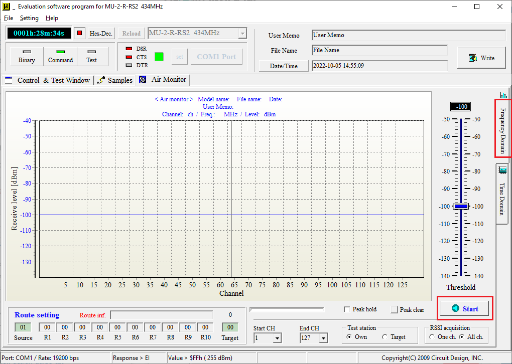
The graph below shows receive level vs frequency channel. The graph is updated with every new collection of readings.
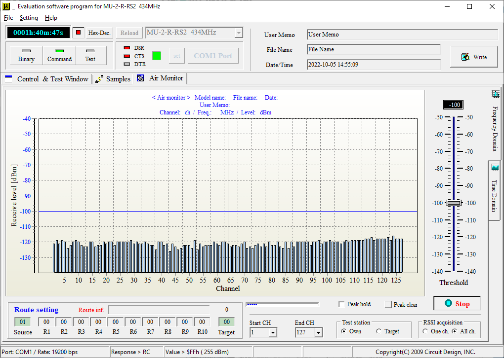
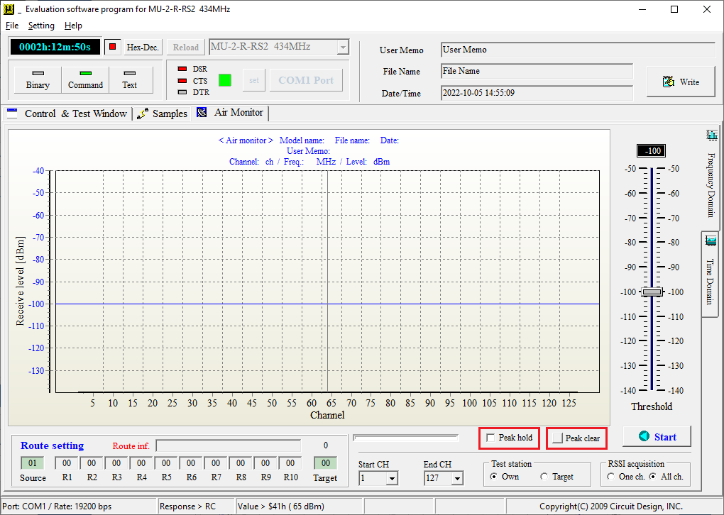
When compared to an actual spectrum analyser, the sweep time (the time between each acquisition of data) takes longer so it is possible to miss short bursts of signal. How the channels are used in your area varies with time and so it can become necessary to monitor over a long time or change the acquisition rate (by setting a narrower channel range for example). Additionally a convenient feature is the "peak hold" function (by checking the "Peak hold" box and unchecking to disable it).
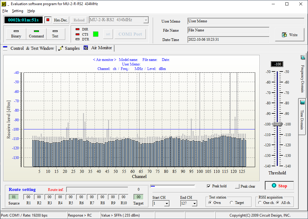
The below graph shows the air monitor after running continuously for 2 hours using the peak hold function. You can see that signals have appeared on channels such as ch100, 118 and 122 along with subtle variations in noise level that would not have been possible to capture with just a few sweeps. By knowing this information, it is possible to see the change in noise level and look for vacant channels. Because the noise level can fluctuate by about 10 to 20 dB, you can account for this variation by including a margin of 10 dB.
Time domain
It is also convenient to observe the received signal on just one channel over a certain time period. By clicking on the tab "Time domain", you can enter the Air Monitor time domain function.
The channel to be measured is selected from the drop down list. The program displays the trace as samples over time. Set the time range (number of samples) and sampling time (interval between samples), measuring mode and press the Start button.
Meas. CH
The channel whose level you want to monitor. 1 to 127 (434 MHz band)
Time range
The number of sampling points per trace. Increase the number of points too much and the trace will be difficult to see and take long to complete. Initially the user should set this to 50 to 100.
Sampling time
Time interval between samples. The minimum is 100ms. If the interval is too long, small variations will not be seen so please set appropriately.
Meas. mode
One shot captures a single trace.
Continue captures the trace repeatedly.
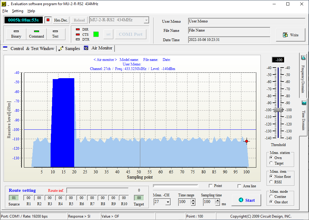
The below graph shows a trace on ch27 indicating a signal occurring once about every minute.
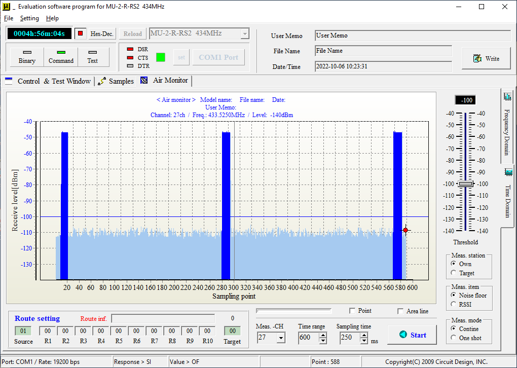
By adjusting the Time range and Sampling time, you can see the signal last for about 1s.
It is also possible to acquire the level of a remote target station by selecting "Target" in "Meas. station" option. The functions are slightly different so refer to the operation guide for details.
When measuring level at the target station, it is not necessary to connect a PC to the target module, only the power supply.
Confirming signal to noise ratio (SNR)
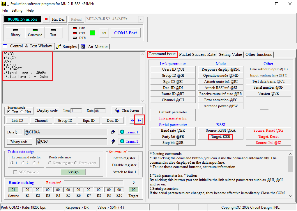
By using the @CR command, it is possible to obtain the signal level and floor noise at the target station.
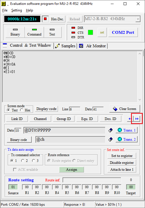
You can enter the @CR command directly into the program or by clicking the arrow below, you can get the view for the extended functions.
When the "Target: RSSI" button is clicked, a packet is sent to the target station and the RSSI during reception of the packet and when there is no packet (noise level) are measured at the target station. The target station then replies back to the source (own) station with these values - with the target RSSI level during reception being above the RSSI level when there is no packet (noise level). The user needs to aim for either a high signal level or a low noise level. The difference between these levels is the Signal to Noise Ratio (SNR). For example, the RSSI level during reception is -90 dBm and the RSSI when there is no reception is -120 dBm. The SNR is therefore -90 -(-120) = 30 dB.
A higher SNR will improve communication but for FSK used by MU-2-R and MU-4-434 modem, reception is possible with a SNR as low as 10 dB. For the most stable communication, it is recommended to try and increase this to 20 dB to allow for some margin.
Packet communication
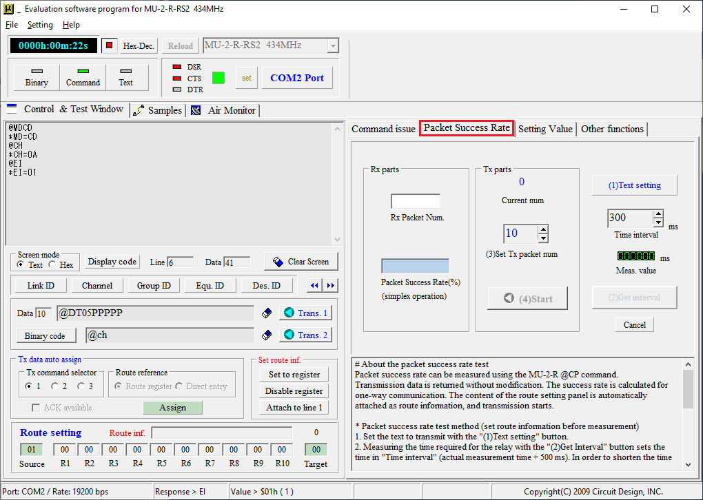
The packet communication function involves sending a pre-determined number of packets to the target which the target station then relays back to the source. During reception from the target, the source station counts how many packets it receives and shows packet success rate. It is recommended to set the packet size comparable to the size that will be used in actual communication.
Like the SNR, pressing the right arrow will open the extended functions where you will find the "Packet Success Rate" tab.
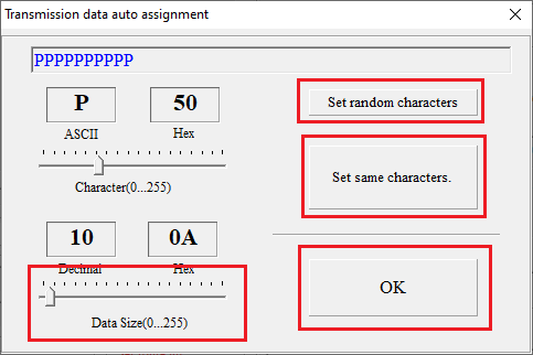
Clicking on "(1)Text setting" will allow you to specify the characters to be sent along with the data size. First you set the data size using the slider. Then by clicking either the "Set random characters" or "Set same characters" you can set random or identical characters of length according to data size. In the case of "Set same characters", the exact character can be specified by using the slider for "Character (0...255)". When the data has been set, press the OK button.
It is possible to indicate the time for a round trip by pressing the "(2) Get interval" button. This will appear in the "Meas. value" as a value in ms. When multiple packets are sent, the "Time Interval" sets the interval between each transmission which can be adjusted by the user (this value is automatically set to "Meas. value" + 500ms whenever the "(2) Get interval" is clicked).
Under "Tx parts", the "(3) Set Tx packet num" will set the number of packets. After this the packet test can be started by clicking "(4)Start".
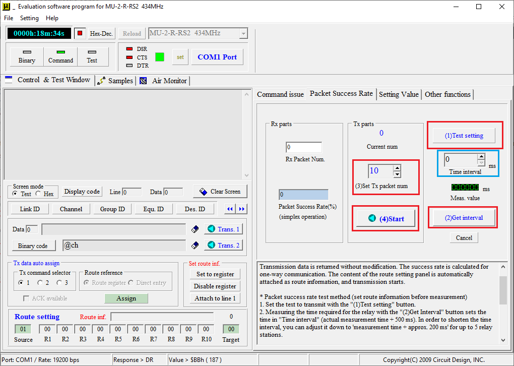
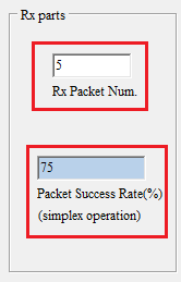
The "Rx parts" shows the count as the replies are received by the source station along with packet success rate in percent. You need to wait until the end of the test to determine the total success rate.
Conclusion
- The article has demonstrated the different methods to confirm the quality of communication, with each method giving different results. So when conducting tests, it is important to consider the results in combination.
- By examining the noise floor and the received signal level the user can obtain the margin.
- The packet test allows the user to measure the communication quality with actual data packets.
- Each method has its own strengths and weaknesses and should be considered in combination.
- Finally, the level and results of the packet tests can be affected by e.g. time of day, weather, season etc. So it is necessary to perform the test several times under different conditions.
