Evaluating MU Series Modems: Establishing Link Feasibility Before Writing Code
Introduction
In this article, we introduce the evaluation tool for evaluating Circuit Design's MU series of radio modems. The evaluation tool, in conjunction with a PC and serial port, allows you to physically test and validate your communication link using a dedicated and intuitive graphical interface.
In particular, the air monitor function in the tool allows you to see (visually) what is happening in your communication link.
What do we mean when we say "Establishing Link Feasibility Before Writing Code"
To streamline the communication system design, we can visualise the communication and the application layers.
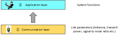
Application and Communication layer
The communication layer optimises the factors needed to make the wireless link work while the application layer optimises the overall functionality of the system. If these phases are not treated separately with the testing of the communication link left to the very end, the communication may not perform as expected. Development time is wasted trying to determine if the problem lies with the radio link or not.
By testing and securing the performance of the wireless link initially using evaluation tools, you can develop the rest of your system functions on top of a stable communication layer.
Testing: Advantages of a visual evaluation tool
When using the PC's serial port, generation of serial data to either configure the module settings (such as channel) or prepare test packets for transmission to a remote receiver is necessary. For Circuit Design's MU series of modems, a proprietary command system handles both module settings and packet generation.
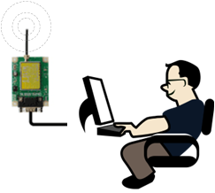
Controlling your radio module using PC
It is possible to write custom programs (either executing list of commands or creating your own serial Windows application) to test a communication link. However this requires time and understanding of the serial commands. A "plug and play" solution such as an evaluation tool allows you to quickly and easily look at the performance through a "point and click" intuitive interface.
MU Evaluation program for MU-4-434
Circuit Design introduces the MU Evaluation program for the MU-4-434 which is compatible with Windows 11. Both Japanese and English interface are covered in one downloadable file.
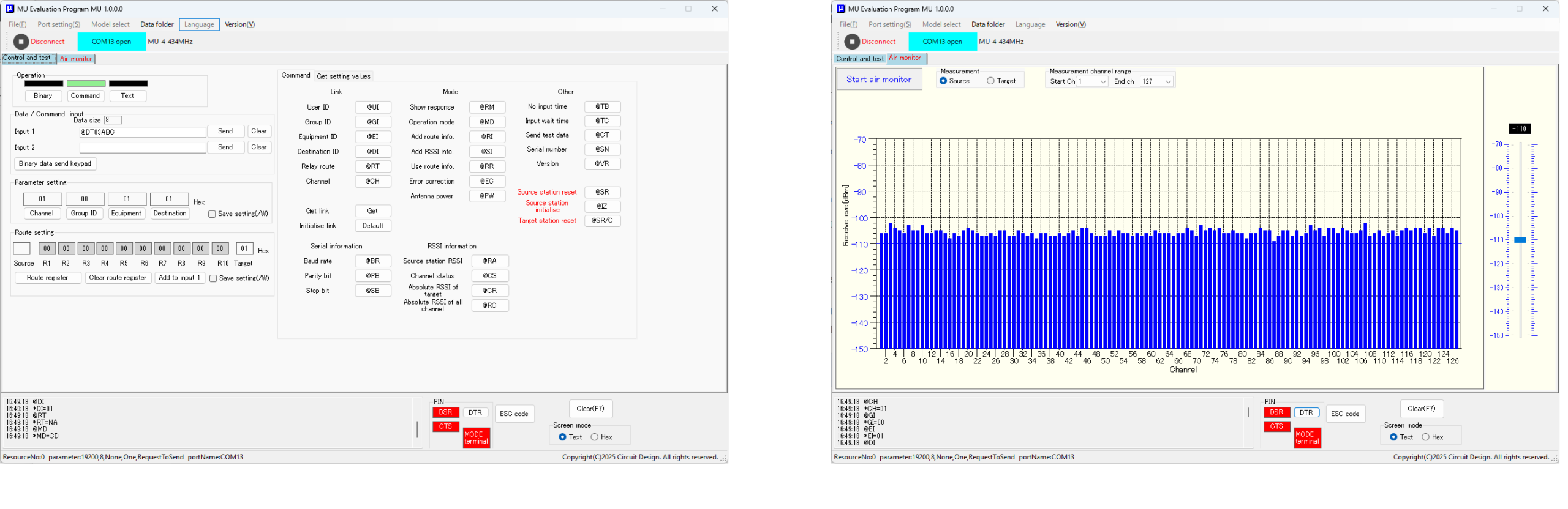
Control and air monitor panel
Prerequisite recommended reading
It is worth reading the article, "Performing field tests" so you can understand the nature of measurements before you undertake them using the evaluation tool. The table below shows how to activate them in the evaluation tool. Explanations for each follow below.
| Measurement | Activation in evaluation tool |
|---|---|
| Noise floor and other signals | Air Monitor |
| Signal to Noise ratio | Command @CR : Acquisition of the RSSI absolute level of the target station |
| Packet testing | Command @CP : Packet test. Send packet to target and reflect back to source unchanged. |
Preparation and Installation
Necessary hardware:
- 2 x either RS232 Interface Board (MU4-RS2IF) or USB Interface Board (MU4-USBIF) for a complete communication test.
- Cable to connect the interface board to the PC. This depends on the board that is either configured for RS232 or USB to exchange serial information.
Setting the display language
Selecting either Japanese or English operation can be done by simply entering the menu here:
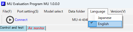
Language selection
Port setting menu
When exchanging serial information, the PC has to match to the hardware its connected to. The PC's serial port name and parameters can be configured in the menus:
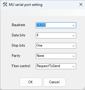
Serial interface setting
The default setting for the MU-4-434 is 19,200 bps.
Serial interface rate vs air rate
Note that "Baud rate" applies to the serial interface between the PC and the radio. Even though that interface rate is configurable, the radio module constrains the overall rate (air rate) that can be used.
For example, the maximum selectable rate between the serial port and the MU-4-434 is 57,600 bps. In contrast, the MU-4-434 modem can achieve an air rate of 4,800 bps with which, accounting for the data framing, provides an effective rate of 3,400 bps (with error correction enabled, this is reduced to 2,300 bps).
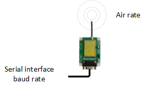
Distinction between interface and air rate. The air rate forms the communication speed of your link.
Compatible models
The MU Evaluation program for MU-4-434 supports the following MU series of modems (excluding the MU-2-R) :
- MU-4-434 (434 MHz)
Additionally, the following modems for operation in Japan are supported:
- MU-3-429 (429 MHz)
- MU-3-1216 (1216 MHz)
- MU-4-429 (429 MHz)
Using the tool
Checking band activity
Seeing the band activity by individually checking each channel's RSSI would be very time consuming. The advantage of creating an evaluation tool is that processes can be automated by the click of a button. The included air monitor feature can produce a graphical output of band activity.
So why would you need to check band activity?
A radio modem or module may have good performance, but if there is noise / interfering signals happening on the same channel as the one you are using, you will experience communication errors. By monitoring the band activity in your area, you can see which channels are being used by other devices and which are free.
The air monitor output shows the RSSI (in dBm) vs channel. The graph is updated after the RSSI for all channels are acquired and is a continuous process. Because of the time needed to acquire the RSSI information and display it, some signal events can get missed. To ensure you capture enough information, it maybe necessary to run this process for an extended period of time.
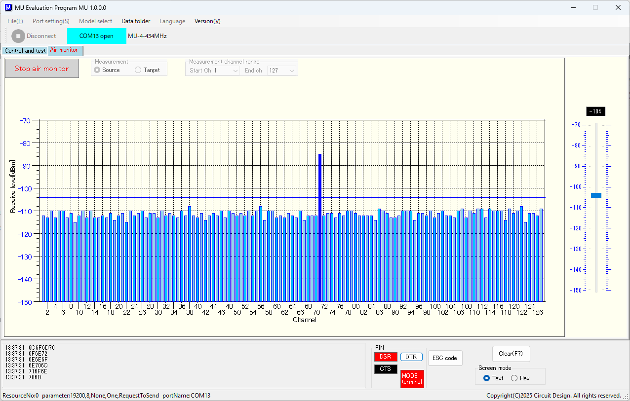
Signal on channel 71
Checking noise level
If you leave the air monitor running over a long time, signal events that occur during the RSSI acquisition are revealed by the peak function. The peak function captures and stores the highest level, so you can look at the maximum noise fluctuation on that channel. The evaluation tool applies the peak function to all channels visible in the air monitor, so its possible to search for vacant channels by comparing the current and peak values.
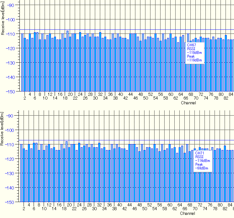
Ch 67 - 0 dB with minimal fluctuation. However Ch 71 shows a fluctuation of 46 dB implying high level of noise (or a presence of another device) on this channel.
Confirming signal to noise ratio at the target station
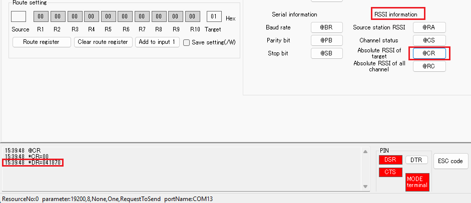
The @CR command initiates a packet transmission to the target station with the target station measuring the RSSI both times - without and with reception of the packet. The source station receives the RSSI information reply from the target and displays it. In this example, "*DR=04 1870" tells us 4 bytes information. The "18" and "70" converts to decimal -24 dBm (signal) and -112 dBm (no signal).
The no signal reading represents the noise on that channel and during reception, a reading of -24 dBm. Therefore the signal to noise ratio in dB seen at the target would be the difference between the two values, i.e. 88 dB.
Packet testing
Packet tests allow you to send packet data to the target which it receives and re-sends back to the source station. The source station can verify the packet from the target and, by sending/receiving packets repeatedly, you can count the number of successful packets. You can therefore estimate the packet success rate of your link.
You can perform packet testing in two ways:
- By issuing the command manually
- Download and use the legacy "MU-2-R Evaluation Software Program".
By issuing the command manually
In the "MU Evaluation program for MU-4-434", you can enter commands manually and see the response in the output screen:
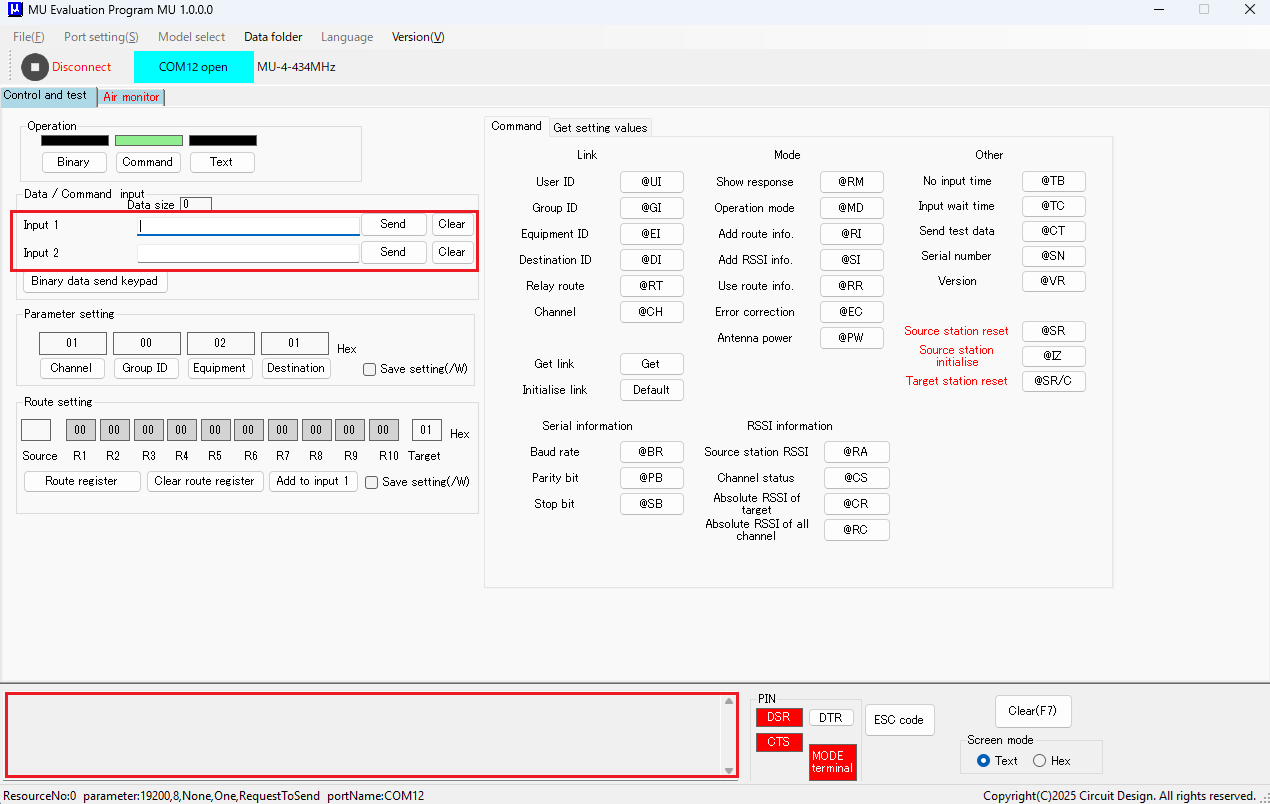
Command input and output screen
The "@CP" command attaches the specified bytes and sends them to the target station. For example, to send the following bytes that represent characters: [C] [i] [r] [c] [u] [i] [t] for example, you issue:
@CP07Circuit CRLF
The "07" means you are sending 7 bytes and the command ends with the terminator (CRLF). The command acknowledgement is:
*CP=07 CRLF
You receive the reply from the target:
*DR=07Circuit CRLF
To determine the success rate, you need to repeat this process a set number of times. When the test is finished, you can:
Examine the output screen and count the number of occurrences of the string"@CP07Circuit". This corresponds to number of packets sent.
Examine the output screen and count the number of occurrences of the string "*DR=07Circuit". This corresponds to number of packets received.
To determine the success rate: (Number of packets received successfully / Number of packets sent) x 100
MU-2-R Evaluation Software Program
As we have seen, performing the packet test in such a manner involves issuing the correct commands and to do a manual count to get the success rate. Automating the entire process using a point and click interface makes this fast and efficient, and tests can be performed right away. The "MU-2-R Evaluation Software Program" provides a dedicated interface for packet testing as described below.
When you open the evaluation program, clicking on the packet success rate tab brings up the interface for packet testing:
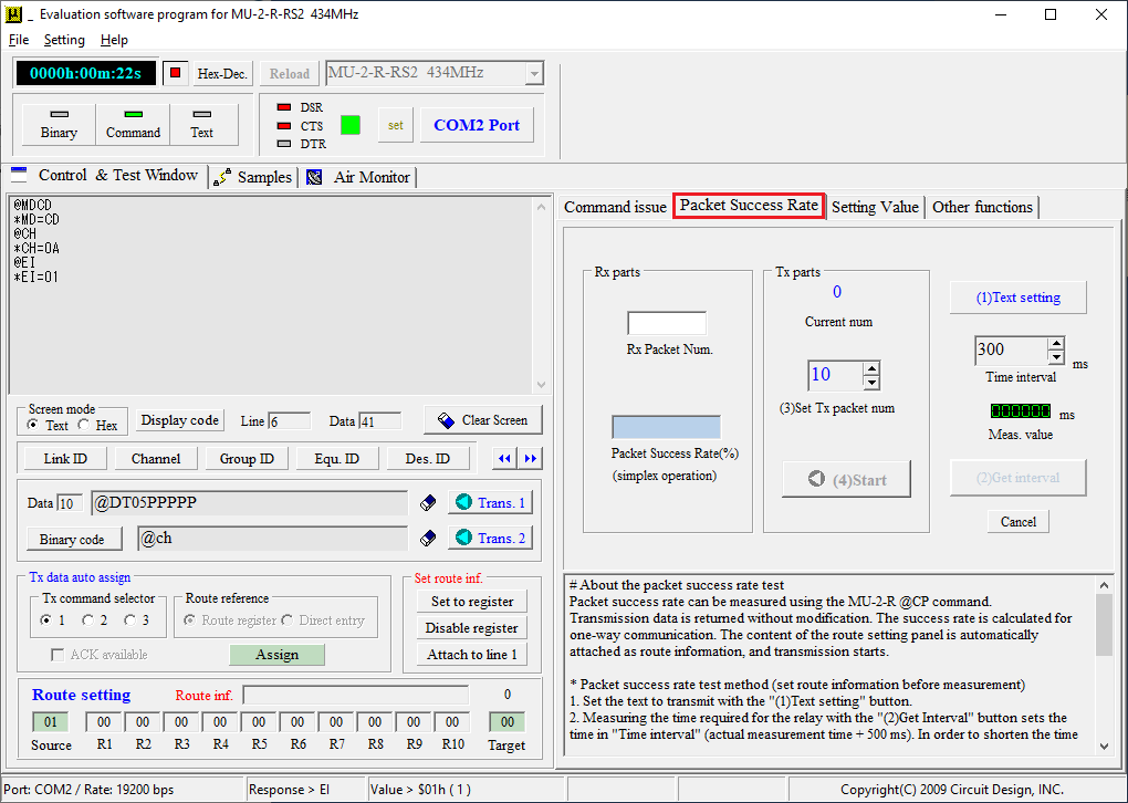
Clicking the [>>] button brings up the extended functions. Clicking the "Packet Success Rate" brings up the interface for packet test.
A separate control panel by clicking "(1)Text setting" allows you to prepare a data packet (random set or specific character). You can also set the size, i.e. the same size as the your actual data.
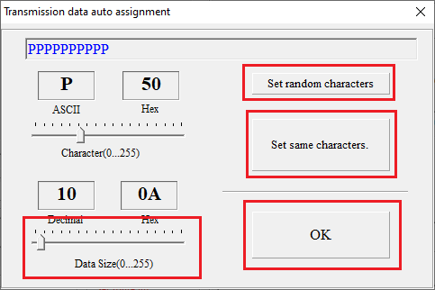
Note that this method does not allow input of user data. To use own data, use the "command" method for packet testing
The "(2) Get interval" instructs the modem to send out a packet and measure its round trip time. This time is displayed in the "Meas. value".
The "Time interval" sets the interval between transmissions. By default this is equal to Meas. value + 500ms.
The "(3) Set Tx packet num" sets the number of packets to be sent.
When you click "(4) Start", the packet test begins. You can see the results in real time under "Rx parts" with the number of packets received vs packet success rate, but you need to wait for the test to end so you can obtain a definitive result.
A 100% rate means all packets sent and received with no errors.
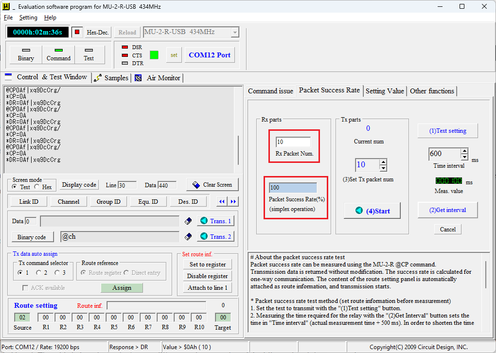
For 10 packets sent: A packet success rate of 100% means all 10 packets sent, acknowledged and confirmed with no errors.
Legacy software
The "MU-2-R Evaluation Software Program", the original evaluation tool, is available for download from our site to act as a fall back version. The table below shows the feature differences between the original (legacy) and the new version.
| Feature | Legacy version (MU-2-R Evaluation Software Program) |
New version (MU Evaluation program for MU-4-434) |
|---|---|---|
| General | ||
| Applicable models | MU-2-R | MU-3-429, MU-3-1216, MU-4-429, MU-4-434 |
| Languages | English | English and Japanese |
| Sample transmissions | Bulletin board / File | None |
| Air monitor | ||
| Frequency domain Time domain |
Yes Yes |
Yes No |
| Graph peak hold | Shows peak bars | Shows numerical value |
| Graph options | Yes | No |
| Packet testing | ||
| Packet test controls | Yes | No |
Conclusion
Securing your communication layer in addition to creating the application code is a daunting task. The evaluation tool allows you to create a base line for inspecting channels, fixing acceptable signal to noise ratios and running packet tests to establish a stable working link.
Following this, you can begin to create your system firmware on top of your working radio link with confidence. For further command syntax references, refer to the MU-4 operation guide.